
Applets
contents
visual index
 introduction
 std_logic_1164
 gatelevel circuits
 delay models
 flipflops
 adders and arithm...
 counters
 asynchronous...
 asynchronous...
 frequency di...
 synchronous ...
 synchronous ...
 up/down counter
 asynchrounou...
 749x counters
 7493 1:16 co...
 7490 1:10 co...
 7492 1:12 co...
 74590 counter
 74390 decima...
 frequency co...
 pulse-generator
 digital clock
 digital clock
 LFSR and selftest
 memories
 programmable logic
 state-machine editor
 misc. demos
 I/O and displays
 DCF-77 clock
 relays (switch-le...
 CMOS circuits (sw...
 RTLIB logic
 RTLIB registers
 Prima processor
 D*CORE
 MicroJava
 Pic16 cosimulation
 Mips R3000 cosimu...
 Intel MCS4 (i4004)
 image processing ...
 [Sch04] Codeumsetzer
 [Sch04] Addierer
 [Sch04] Flipflops
 [Sch04] Schaltwerke
 [Sch04] RALU, Min...
 [Fer05] State-Mac...
 [Fer05] PIC16F84/...
 [Fer05] Miscellan...
 [Fer05] Femtojava
 FreeTTS
As frequency is defined as 'pulses per second', it is sufficient to just count pulses during one second (or any other time interval) to measure the corresponding input frequency. To this end, a 'gate' component is used to limit the counting of input pulses to a time interval of known length. Obviously, when the time interval is exactly one second, no additional scaling is necessary, and the final counter value directly corresponds to the frequency of the input signal.
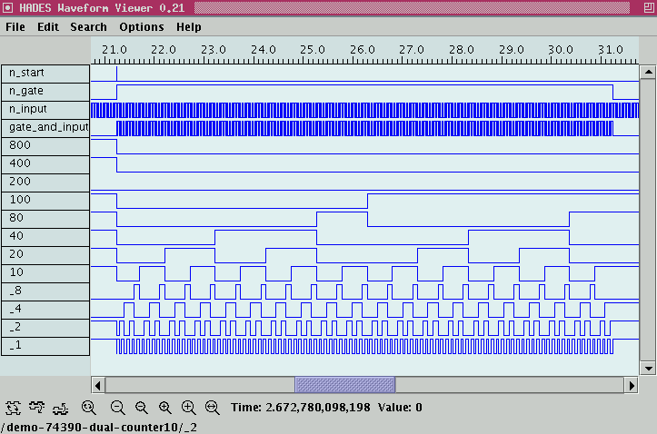
Pressing the 'start' button first resets the 4-digit decimal counter; it also initializes and starts the output pulse from the 'GATE' subdesign. This subdesign uses the reference clock of 100 KHz to create a single 1-second output pulse. (Changing the reference clock also changes the output pulse duration proportionally). The AND-gate masks the input signal to the 'GATE' pulse duration.
The following image shows typical example waveforms during a measurement:

See the next applet for the internals of the GATE subdesign which is also built from 74390 components. The idea is to create a highly accurate pulse duration in the range of seconds by counting thousands (millions) of short pulses, instead of trying to create a single pulse of the required length. While the latter is very difficult with electronical components, a cheap (temperature-stabilized) quartz-oscillator can be used to generate a very precise signal in the few-MHz range.