
Applets
contents
visual index
 introduction
 std_logic_1164
 gatelevel circuits
 delay models
 flipflops
 adders and arithm...
 counters
 asynchronous...
 asynchronous...
 frequency di...
 synchronous ...
 synchronous ...
 up/down counter
 asynchrounou...
 749x counters
 7493 1:16 co...
 7490 1:10 co...
 7492 1:12 co...
 74590 counter
 74390 decima...
 frequency co...
 pulse-generator
 digital clock
 digital clock
 LFSR and selftest
 memories
 programmable logic
 state-machine editor
 misc. demos
 I/O and displays
 DCF-77 clock
 relays (switch-le...
 CMOS circuits (sw...
 RTLIB logic
 RTLIB registers
 Prima processor
 D*CORE
 MicroJava
 Pic16 cosimulation
 Mips R3000 cosimu...
 Intel MCS4 (i4004)
 image processing ...
 [Sch04] Codeumsetzer
 [Sch04] Addierer
 [Sch04] Flipflops
 [Sch04] Schaltwerke
 [Sch04] RALU, Min...
 [Fer05] State-Mac...
 [Fer05] PIC16F84/...
 [Fer05] Miscellan...
 [Fer05] Femtojava
 FreeTTS
Click the clock switch or type the 'c' bindkey to operate the counter. (To keep the schematics as readable as possible, separate power-on-reset components are used for each flipflop in the example. No bindkeys are used for the power-on-reset components.)
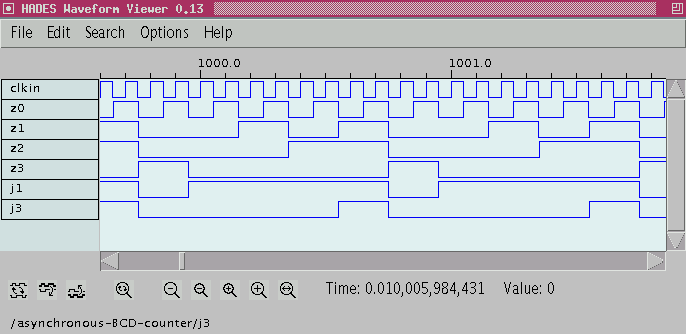
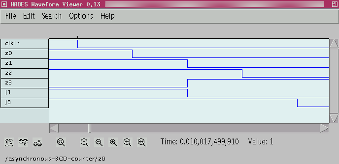
The basic structure is just the asynchronous counter, with the Q output of one counter stage used as the CLK input for the next stage. Due to the AND-gate in front of its J input, the Z3 flipflop is only set when both Z1 and Z2 are 1 and Z0 generates a 0-1 edge. These conditions are only met when counting from seven to eight, correctly setting the Z3 flipflop. At the next clock input to Z3, while counting from nine to ten, the J input of Z3 is zero and the flipflop is reset to 0. At the same time, flipflop Z1 is also reset the NQ output of flipflop Z3 is still zero, inhibiting the transition of Z1 to 1, so that the counter correctly counts from nine to zero. The following image shows the timing diagram with the counter output, when the input clock frequency is very slow compared to the gate delays. However, when zoomed into the timing diagram, the asynchronous nature
of the counter becomes clearly visible.
The individual flipflops do not toggle state at the same time,
but rather one after another.
While the asynchronous counter can be run at very high clock frequencies,
it is unsuitable for integration into synchronous designs.
 For a detailed discussion of counters,
see (Jutzi, Digitalschaltungen, 4.3.3, p.137).