
Applets
contents
visual index
 introduction
 std_logic_1164
 gatelevel circuits
 delay models
 flipflops
 adders and arithm...
 counters
 LFSR and selftest
 memories
 programmable logic
 state-machine editor
 misc. demos
 I/O and displays
 DCF-77 clock
 relays (switch-le...
 CMOS circuits (sw...
 RTLIB logic
 RTLIB registers
 Prima processor
 D*CORE
 MicroJava
 Pic16 cosimulation
 Mips R3000 cosimu...
 Intel MCS4 (i4004)
 MCS4 Overview
 MCS4 binary ...
 MCS4 BCD add...
 MCS4 binary ...
 MCS4 BCD sub...
 MCS4 RAM add...
 MCS4 RAM sub...
 MCS4 increment
 MCS4 increme...
 MCS4 calculator
 i4003 shift-...
 MCS4 I/O ports
 MCS4 Counter
  image processing ...
 [Sch04] Codeumsetzer
 [Sch04] Addierer
 [Sch04] Flipflops
 [Sch04] Schaltwerke
 [Sch04] RALU, Min...
 [Fer05] State-Mac...
 [Fer05] PIC16F84/...
 [Fer05] Miscellan...
 [Fer05] Femtojava
 FreeTTS
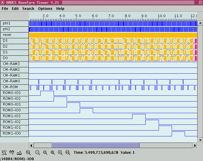
The software running on the i4004 microprocessor consists of a simple endless loop that writes the bit-patterns 1000, 0100, 0010, 0001 to the first ROM chip, and then to the next ROM chip via the WRR instruction. In between, a little bookkeeping is necessary. To demonstrate this better, the circuit uses a very slow clock period (0.05 seconds).
; lauflicht.asm
;
; MCS4 (i4004) program to demonstrate accessing the i4001 ROM chip ports.
; The circuit uses one i4004 CPU and two i4002 ROM chips.
;
; (C) 2003, 2004, 2005 by
; Andreas Ruge and Norman Hendrich
; Univ. of Hamburg, Dept. CS
;

START
	FIM R0R1, 0x24	; R0=2, R1=4
	FIM R2R3, 0x00	; R2=0, R3=0

	SRC R2R3	; select ROM chip #0
	LDM 8		; load value 8 (1000)
	WRR		; and write to ROM output
	LDM 4		;
	WRR		; write value 4 (0100) to ROM output
	LDM 2		;
	WRR		; write value 2 (0010) to ROM output
	LDM 1		;
	WRR		; write value 1 (0001) to ROM output
	LDM 0		;
	WRR		; write value 0 (0000) to ROM output

	CLB		; code to select ROM chip #1
	IAC		;
	XCH R2		;
	SRC R2R3	;

	LDM 8		; load value 8 (1000)
	WRR		; and write to ROM output
	LDM 4		;
	WRR		; write value 4 (0100) to ROM output
	LDM 2		;
	WRR		; write value 2 (0010) to ROM output
	LDM 1		;
	WRR		; write value 1 (0001) to ROM output
	LDM 0		;
	WRR		; write value 0 (0000) to ROM output

	JUN START	; jump back (endless loop)
The following screenshot shows example waveforms produced during the simulation:

See also:
- Overview of the MCS4/i4004 microprocessor system.
- Rekonstruktion und Visualisierung von Systemen mit Intel 4004 Prozessor, p.32-35.