
 |  |
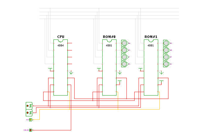
 DescriptionThis demonstration shows how to use the output ports
of the 4002 integrated circuits to control external circuitry.
To visualize the logic values on the output ports,
a few LED components are connected to them.
The software running on the i4004 microprocessor consists of a simple endless loop that writes the bit-patterns 1000, 0100, 0010, 0001 to the first ROM chip, and then to the next ROM chip via the WRR instruction. In between, a little bookkeeping is necessary. To demonstrate this better, the circuit uses a very slow clock period (0.05 seconds).
; lauflicht.asm
;
; MCS4 (i4004) program to demonstrate accessing the i4001 ROM chip ports.
; The circuit uses one i4004 CPU and two i4002 ROM chips.
;
; (C) 2003, 2004, 2005 by
; Andreas Ruge and Norman Hendrich
; Univ. of Hamburg, Dept. CS
;

START
	FIM R0R1, 0x24	; R0=2, R1=4
	FIM R2R3, 0x00	; R2=0, R3=0

	SRC R2R3	; select ROM chip #0
	LDM 8		; load value 8 (1000)
	WRR		; and write to ROM output
	LDM 4		;
	WRR		; write value 4 (0100) to ROM output
	LDM 2		;
	WRR		; write value 2 (0010) to ROM output
	LDM 1		;
	WRR		; write value 1 (0001) to ROM output
	LDM 0		;
	WRR		; write value 0 (0000) to ROM output

	CLB		; code to select ROM chip #1
	IAC		;
	XCH R2		;
	SRC R2R3	;

	LDM 8		; load value 8 (1000)
	WRR		; and write to ROM output
	LDM 4		;
	WRR		; write value 4 (0100) to ROM output
	LDM 2		;
	WRR		; write value 2 (0010) to ROM output
	LDM 1		;
	WRR		; write value 1 (0001) to ROM output
	LDM 0		;
	WRR		; write value 0 (0000) to ROM output

	JUN START	; jump back (endless loop)
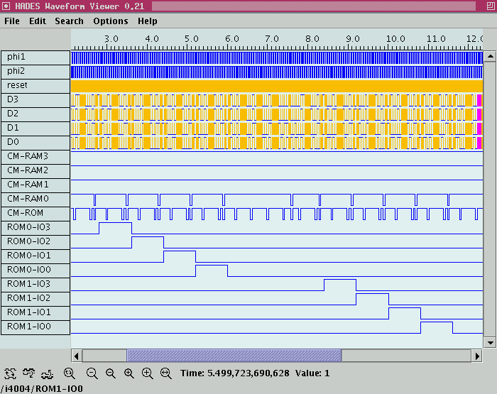
The following screenshot shows example waveforms produced during the simulation:

See also:
Run the applet | Run the editor (via Webstart)