
PalCo
A Digital PAL Video Signal Encoder in a FPGA
DSP'99The pure digital PAL encoder contains all signal processing components necessary for generation of a composite PAL video signal. The PAL encoder converts YUV components [8:4:4] into digital composite PAL video signal. A timer generates an interlaced synchronization signal scheme and some internal control signals. A sine wave generator (DDS = Direct Digital Synthesis) generates the PAL color carrier signal (4.433,816,75 MHz) from a generic digital clock. Fast phase selection allows choosing one of four phases (0°, 90°, +135°, -135°) for the burst signal (A/B) and for the QAM modulation (QAM = Quadratur - Amplitude - Modulation) of both color difference signals U and V required for the chrominance signal C generation. The sample frequency (15 MHz) is half of the clock frequency (30 MHz). A video mixer merges the digital luminance signal Y with the digital chrominance signal C and switches black signal level and synchronization signal level. This results in a digital composite PAL video signal. The implemented PAL encoder has following block structure:
The VHDL behavioural description of the PAL encoder could been validated easily with the following FPGA prototype card. Validation by VHDL simulation is very run-time consuming (30 minutes for a frame sequence of just 0.16 seconds of real time). The component YUV-DEMO generates a digital YUV data stream to be displayed on a color TV - luminance is varied slowly. So, the whole YUV [8:4:4] color space displayable for the pal encoder prototype is passed through.
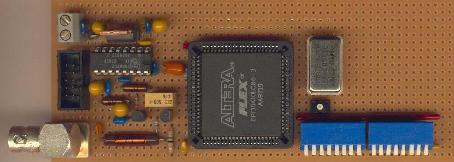
The digital composite PAL video signal of the FPGA prototype is converted to an analog video signal for a standard color TV by a video DAC. So, one can estimate the consequences of numerical approximations - necessary for the hardware implementation of the digital PAL video signal encoder - on the system level.
All of components of the PAL encoder have been designed using VHDL. The design is done within the scope of the PhD project of Lars Larssson. The digital PAL encoder is a case study of a system, where interactions of the design with system components of the environment are essential for the validation of the design itself.

The image displayed above is a result of a VHDL simulation of the digital PAL encoder. These is Y = 0, and U, V are functions of column and row. The composite video signal from the VHDL simulation was written to a file. An executable specification (program written in C language) of a digital PAL decoder (color frame grabber) has been used to extract the color frame from the composite video signal file. The image quality of the digital PAL video signal encoder is better on a real (analog) color TV. The synthesizable VHDL model of the PAL video signal encoder is simplified compared to an executable specification (program written in C language) of a digital PAL encoder, to be compatible with the small FPGA used for rapid prototyping. The executable specification of the PAL encoder reaches an images quality comparable with a consumer video camera. This could be demonstrated with a bidirectional video signal interface VidTrans.
technical Data
| FPGA | 1 x Altera FPGA Typ EPF10K10LC84-3 |
| TIMER | h-sync, v-sync, burst gate, black level, interne control signals |
| DDS | digital sine wave generator for PAL color carrier (4.433,618,75 MHz) |
| QAM | modulation : C = U*sin(wt) + V*cos(wt) |
| MIXER | FBAS = ( Y + C ) & dark & A/B burst & composite sync |
| gate equivalents | ~ 6k |
| pads | 84 |
| Video-DAC | Philips TDA8702 |
| system clock frequency | 30 MHz |
| sample frequency | 15 MHz |
| YUV [8:4:4] | Y[8 Bit, unsigned] : U[4 Bit, signed] : V[4 Bit, signed] |
| digital composite PAL video signal | 8 Bit [unsigned] |