
 |  |
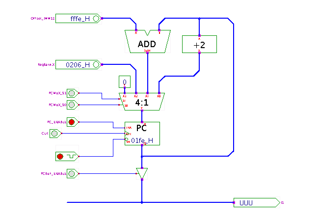
 DescriptionA demonstration of the D*CORE processor program counter logic.
This applet is used in the context of the T3 laboratory course
for interactive exploration of a typical microprocessor control-unit.
The applet shows the logic used to generate both the normal sequential control flow and the several variants of jumps in the D*CORE processor. The PC register always stores the address of the current program instruction; the tri-state driver is enabled during the corresponding cycles of the instruction-fetch microcode to drive the internal data-bus and transfer the PC contents to the MAR register.
The 4:1-multiplexer is used to load one of four different values into the PC register:
PC := regX jump instruction.
PC := PC + 2.
Given the instruction size of 16 bits and the byte-addressing,
the increment of 2 corresponds to the next sequential instruction address.
For details, check the course material (in German) on our webserver.
Run the applet | Run the editor (via Webstart)