
 |  |
 Description
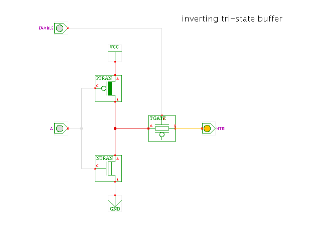
A transmission-gate variant of the CMOS tri-state buffer.
The buffer shown here consists of a standard CMOS inverter following by a CMOS transmission gate. AS a consequence, the output of the gate is the inverse of the data input while the transmission-gate is enabled (conducting), and floating whenever the transmission-gate is disabled.
Again, the simulation model of the t-gate only uses the positive control-input, while actual t-gate require both the positive and the negated control-input. An extra inverter might be required to generate the inverted control input.
Run the applet | Run the editor (via Webstart)