
 |  |
 Description
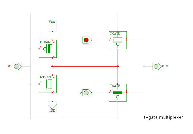
This circuit demonstrates the basic transmission-gate multiplexer.
Click the input switches or type the 's', 'a', 'b' bindkeys
to control the circuit.
The idea behind this circuit is to use two transmission-gates as simple switches to propagate either input A or input B directly to the output. The extra inverter generates the inverse of the SEL select input. While the upper transmission-gate is activated by SEL, the lower transmission-gate is activated by !SEL, due to the wiring of their control (gate-) inputs.
When SEL is low, only the lower transmission-gate is conducting (because !SEL is connected to its n-channel and SEL to its p-channel transistor gate inputs), while the upper transmission-gate is non-conducting. As a result, the value of A is passed through to the output of the multiplexer.
When SEL is high, the upper transmission-gate is activated, while the lower transmission-gate is non-conducting. Therefore, the value of B is passed through to the multiplexer output.
Run the applet | Run the editor (via Webstart)