
 |  |
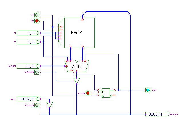
 DescriptionA demonstration of the D*CORE processor datapath
with three-port register bank and custom arithmetic-logic unit.
This applet is used in the context of the T3 laboratory course
to demonstrate the execution of arithmetic instructions
on typical RISC processors.
As shown in the applet, the datapath consists of the register file, whose two read-ports (data-outputs) DY and DX feed the A and B inputs of the arithmetic-logic unit (ALU), while the current function is selected via the ALU_OPC input. Open the ALU property-sheet (popup-menu, edit component) to see (or temporarily change) the various arithmetic and logic operations assigned to the ALU function select input.
The output of the ALU is fed back into the write port of the register file. While most 32-bit and 64-bit processors reserve three different register indexes (register addresses) in their instruction format, the typical 16-bit RISC instruction format (like M*CORE and D*CORE) is restricted to two registers. In the D*CORE instruction set with its 16 registers, each register index takes 4 four bits, so that only 8 bits remain to encode the instruction opcode in the 16 bit instruction word. Therefore, one register is used as both the source and the target of a typical arithmetic or logic operation, e.g.:
  reg_1 = reg_1  "+"  reg_0
  reg_5 = reg_5  "-"  reg_3
  reg_7 = reg_7 "AND" reg_15
Note that the register bank simulation component provides three separate address inputs for its two read ports and single independent write ports. However, due to the instruction-size restriction explained above, the same address input is used for the X read port and Z write port.
The flipflop is used to store and manipulate (enable and update) the carry-flag; it is connected between the carry-output and the carry-input of the ALU. In the full processor, the C_OUT output signal is connected to the control unit, which checks the carry status for conditional branch instructions.
Use the several switches to first initialize the register file, then try to execute a few arithmetic and logic instructions via the datapath. Hint: the ALU opcode 20 (0x14) selects the 'PASS IMM4' operation, which allows to generate a well-defined ALU output value even if both ALU A and B inputs are undefined.
For details, check the course material (in German) on our webserver.
Run the applet | Run the editor (via Webstart)