
 |  |
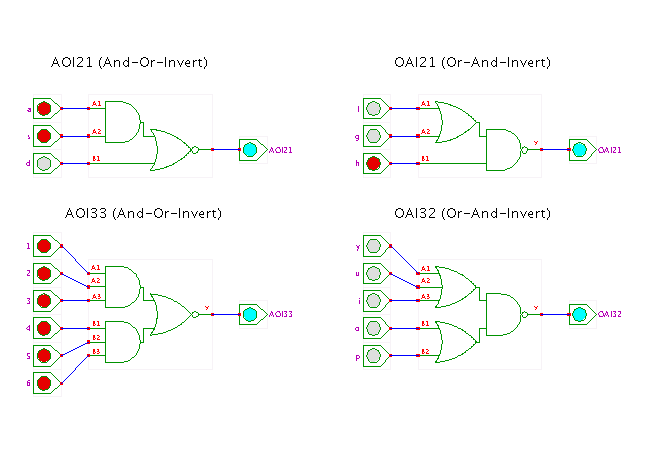
 DescriptionA demonstration of a few complex logic gates,
namely the OR-AND-INVERT and OR-AND-INVERT gates.
Click the input switches to toggle the corresponding input value between 0 and 1, and watch the resulting behaviour. You can also use shift+click to toggle the input value between the states 0, 1, Z (tri-state, not driven) and X (undefined).
The names of these gates are derived from their AND-OR-INVERT and OR-AND-INVERT structure and the number of inputs of the first level gates. To give another example, an OAI222 gate (not shown in the applet) is equivalent to three two-input OR gates that drive a three-input NAND gate.
Complex gates are often used in CMOS VLSI chip design because they can be realized very efficiently, based on clever combinations of series- and parallel-connected transistors. For example, the AOI33 gate can be built using just 12 transistors, while the corresponding discrete realization would require 4 transistors for the NOR gate, and 8 transistors for each AND3 gate for a total of 20 transistors - almost twice as expensive and twice as slow.
Visit our CMOS technology applet page for a detailed (switch-level) demonstration of a complex gate.
To explore the circuit, just click the corresponding switches, or type the following keys:
Run the applet | Run the editor (via Webstart)