
 |  |
 Description
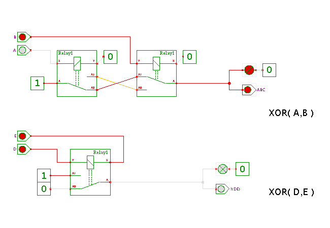
Two ways to realize the XOR function with relays.
Click the input switches or type the ('a','b') and ('d','e') bindkeys to control the circuit and watch the behavior.
The first circuit shows the standard realization with two separate relays, each driven by one input, and the opposite coil input connected to ground. As such, the relay will activate whenever the corresponding input (A,B) is at high level. The cross-connection between the switches realizes the XOR function. Similarly, a straight-connection between the switches would be used to build the XNOR function. Again, a high-output value at the gate output is interpreted as a logical 1, while an unconnected (floating) output is interpreted as a logical 0.
The lower circuit illustrates the fact that a relay will activate when a current flows through its coil, regardless of the current's polarity. In the switch-level simulation, this means that the relay will activate whenever one input of the coil is at (strong) high level and the other at (strong) low level. Note that the circuit shown here will only work if the D and E inputs are strongly driven. As several of the gates shown in the previous applets only provide a strong 1 but a weak (floating) 0, these gates can only be used with the upper XOR gate shown here.
Run the applet | Run the editor (via Webstart)