
 |  |
 Description
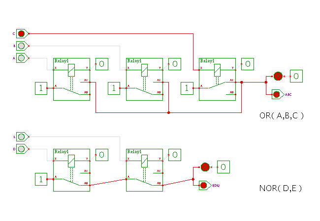
This applet demonstrates a three-input logical OR and
a two-input logical NOR built with relays.
Click the input switches or type the ('a','b','c') and ('d','e') bindkeys to control the circuit and watch the behavior.
The upper circuit uses three relays, with the coil of each relay connected to one input and ground. Therefore, the relays will activate whenever their corresponding input is driven to a (strong) high level.
A parallel connection of the switches insures that the output of the OR gate is driven high as long as at least one relay is active. The net result is the logical OR of the three inputs. Again, a strongly-driven high-value at the output is interpreted as a logical 1, while an open (floating) output is interpreted as a logical 0.
The lower circuit demonstrates a NOR-gate with two inputs. Here, the series-connection of the relay switches ensures that the output will be logical-0 (floating) as soon as one relay activates.
Run the applet | Run the editor (via Webstart)