
CUBE-M...
A new improved modular robot named CUBE-M is developed recently, which is based on the cooperation with Ph.D. Juan González-Gómez from the School of Engineering, Universidad Autonoma de Madrid in Spain. Firstly, it is called GZ-I module.
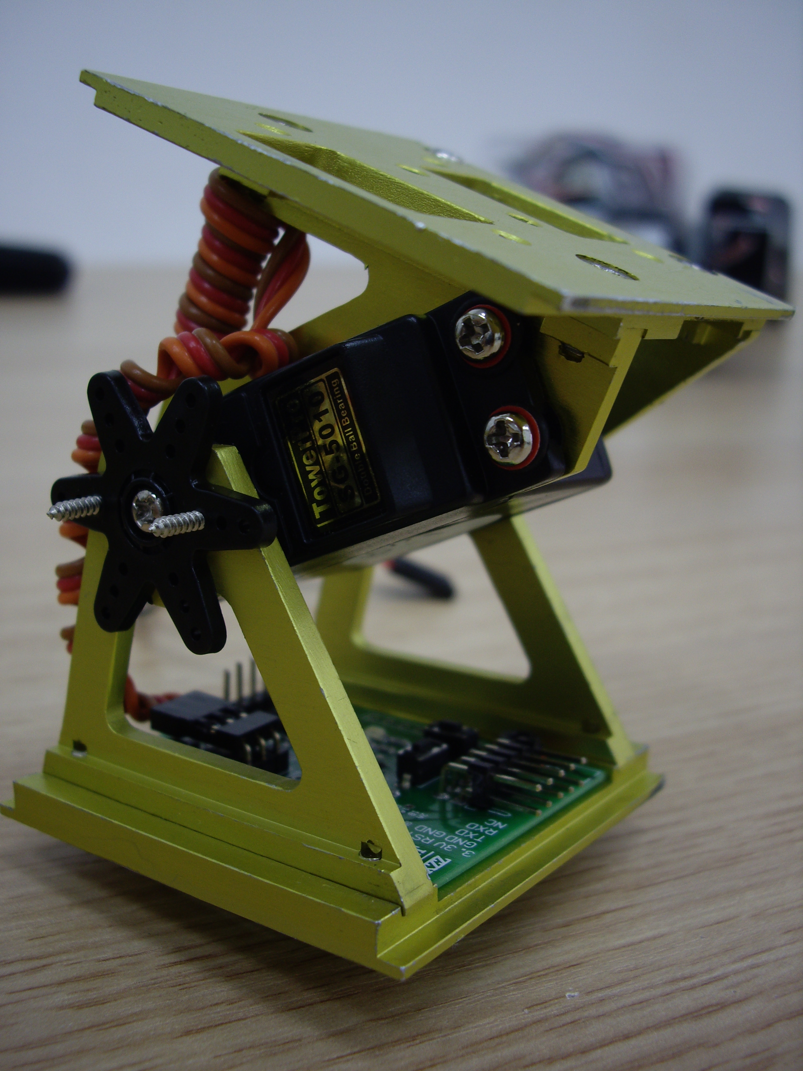
Based on Y1, the following project was aimed at developing a real low-cost, robust, fast-prototyping modular robot with an onboard controller and sensors and a friendly easy-to-use programming environment for testing and evaluating inspired technology. We have been improving GZ-I since 2006. A module is about 80 mm long, 50 mm wide and 50 mm high, as shown in Fig. 4. It consists of six mechanical parts, a RC servo and an electrical controller with enough input and output resources. CUBE-M features the following aspects [51]:
1) Low-cost mechanical design with only six parts in aluminum making up a strong module;
2) Simple robust modules assembling manually and quick-to-build, easy-to-handle design;
3) Four faces for interconnecting modules to implement pitching and yawing movements and two crossed connecting modes so that the system can be extended to build different kinds of inspired robots
4) Onboard controller and sensors completing the system and making sensor-servo-based active perception of the environment possible.
|
|
| Fig. 1 CUBE-M Mechanical Part(GZ-I) | Fig. 2 CUBE-M Design |
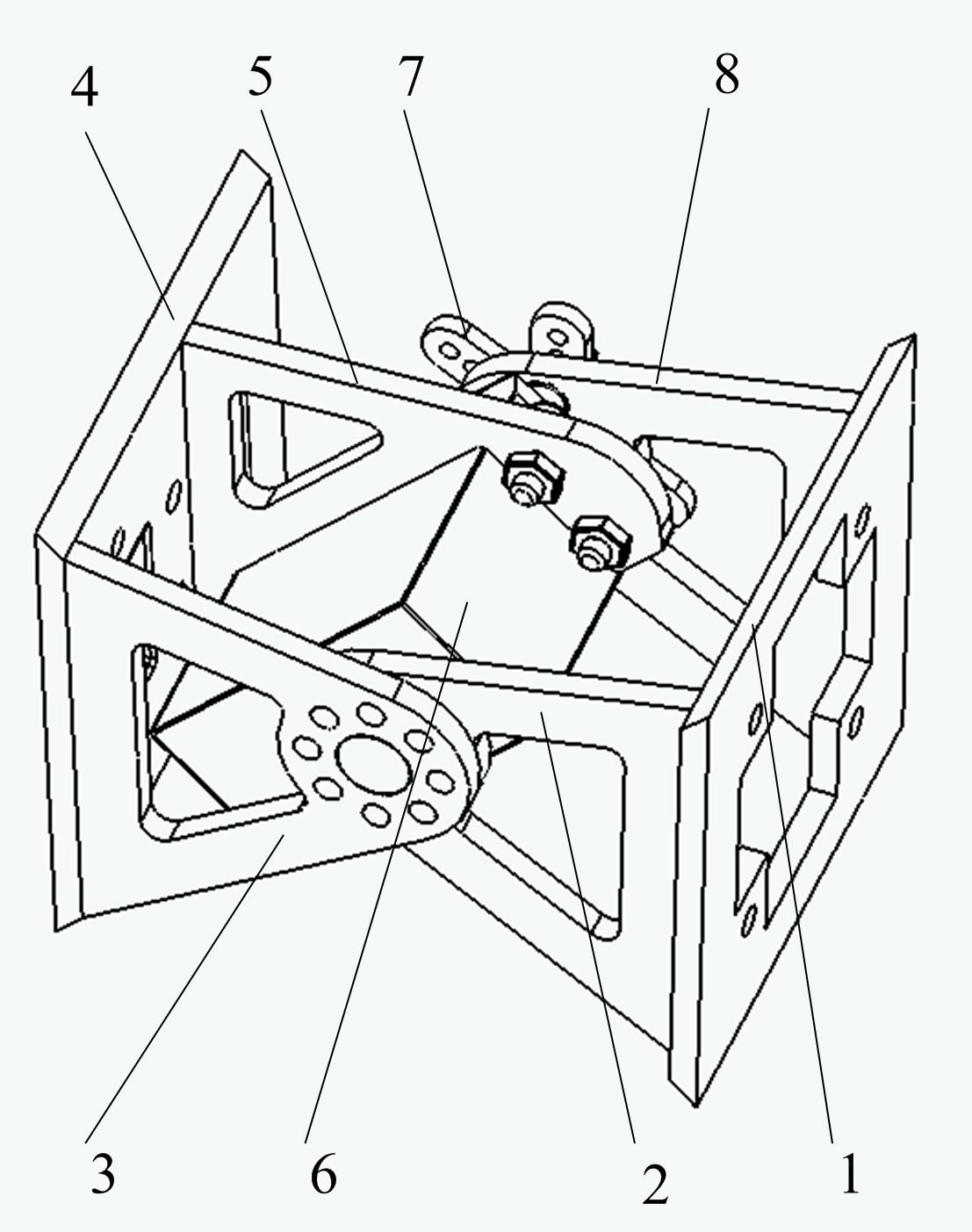
1. Left connecting face; 2. Inboard mechanical ear for rotation output; 3.Outboard mechanical ear for rotation output; 4.Right connecting face; 5. Mechanical bracket for RC servo; 6. RC servo; 7. Rotating plate of RC servo; 8. Mechanical ear for rotating plate
How to build one module
CUBE-M features easy-handling, fast-building and low cost mechanical design and efficient control algorithm for the active joints which endow the robot with the ability of changing shape in two dimensions. Using docking blots, the modules can connect or disconnect easily and flexibly. Each joint actuated by a RC servo is controlled by means of a sinusoidal oscillator with four parameters: amplitude, frequency, phase and offset.
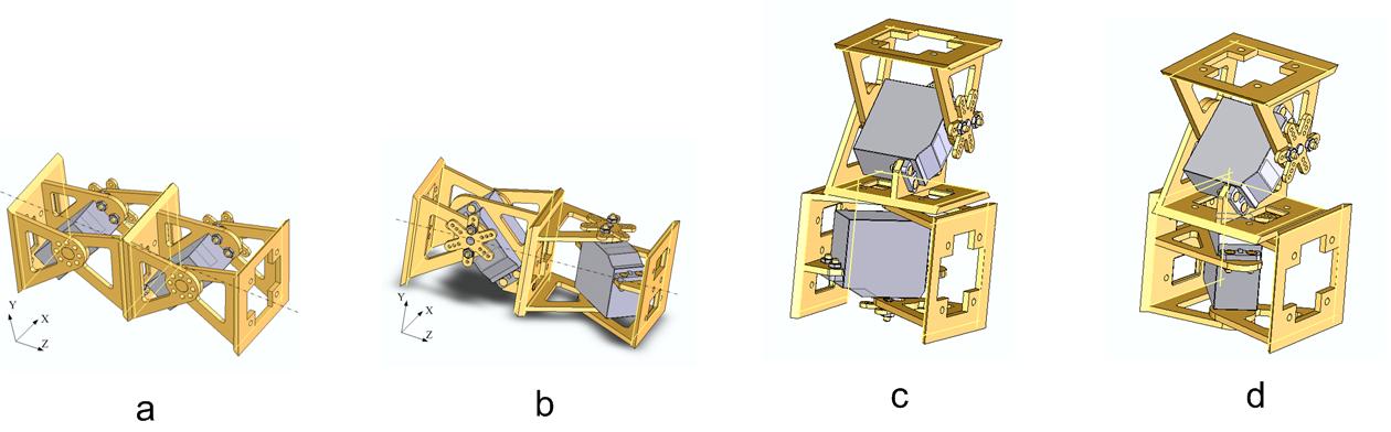
Cube-M can be assembled easily. Firstly the driving RC servo is fixed to mechanical ear 5 using bolts through four holes; while the rotating plate of the servo is fixed to mechanical ear 8. Then we fix the mechanical ears 2 and 8 with the rotating plate to the left connecting face by bolts respectively. This completes the left half of the Cube-M module. In the same way, the mechanical ears 3 and 5 with the RC servo will be fixed to the right connecting face. After that, the left half and right half are brought together. Then the two modules will connect automatically as soon as the rotating plate is fixed to the servo again. In this way, Cube-M will be assembled around the horizontal axis. As a result of being actuated by the servo, one DOF active rotating joint within ±90 degrees enables the left and right half of the module to carry out pitching movements. There are four assembling faces on the Cube-M to implement connections so that the system can be extended to build different kinds of inspired robots. They are attached to the mechanical parts 1, 4, 3, and 7 respectively. They feature holes and screw threads so that any two modules can connect or disconnect easily through bolts. The flexible assembly principles are illustrated in the folllowing figure.

|
| Fig. 3 Build One Module |
There are four assembling faces on the Cube-M to implement connections so that the system can be extended to build different kinds of inspired robots. They are attached to the mechanical parts 1, 4, 3, and 7 respectively. They feature holes and screw threads so that any two modules can connect or disconnect easily through bolts. The flexible assembly principles are illustrated in the folllowing figure.
All connection modes endow the robot with the ability of changing its shape in two dimensions. Some prototypes are built to test different locomotion capability recently.
|
| Fig. 4 Four Connections |
Different configurations
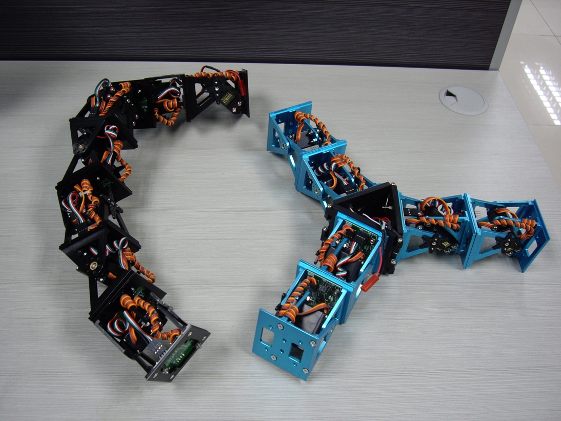
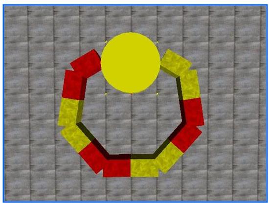
All connection modes endow the robot with the ability of changing its shape in two dimensions. Some prototypes are built to test different locomotion capability recently, as shown below.

|
|
| Fig. 5 Snake-like Configuration using CUBE-M | Fir. 6 Different Configurations |
Control System
The modular robot should own enough intelligence to imitate a natural creature. In order to move freely, firstly it is also important for the robot not to be wired or otherwise connected to the environment. That means each module should carry onboard power, the controller, and wireless communication units. Secondly, as we mentioned before, the system should be low-cost to be used for different applications such as locomotion analysis, bio-inspired investigation.
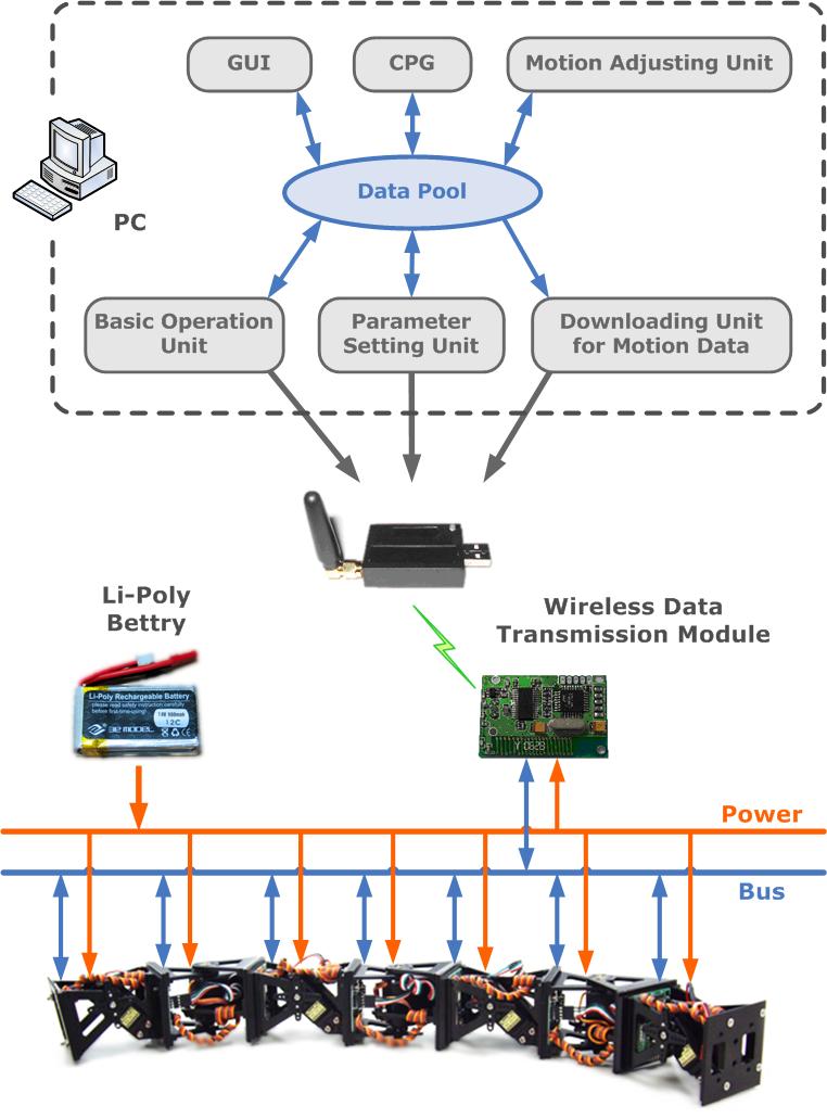
Fig. 7 shows the principle of the control system in a distributed control structure. Each Cube-M module has embedded intelligent capabilities with an independent onboard controller. One hand, each module is equal from the control view point. According to their different locomotion functions, various programs will run on the signal module respectively. All motion commands can be sent to a certain module individually or broadcast to all modules through the IIC bus according to the task requirements. On the other hand, any module can be nominated as a master control which is charge of high-level control functions such as path planning, navigation, localization.
At the moment, a PC is used as a master controlling node. It can also be directly connected to the bus through a set of wireless data transmission modules. In this way, actually the PC can be considered as a virtual module in the robot system and plays the role of the master or a graphic user interface (GUI). There are six units in total in the PC indeed. Except GUI, the parameter setting unit is used to configure the communicate protocol; the basic operation unit is needed for normal operation. For motion control, a Central Pattern Generators (CPGs) unit is to control the oscillation of the RC motors. Due to the mechanical assembly errors and the different qualities of RC motors, a motion adjusting unit is very necessary to make sure that the CPGs can be implemented on each module. In the end, the downloading unit is for the data transformation.
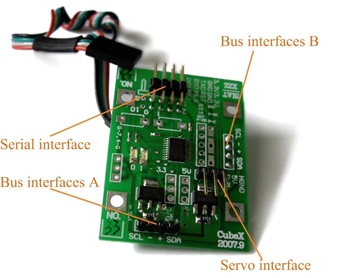
The core part of the system is a CubeX controller, as shown in Fig. 8. P89LPC922 is used as a micro processor with a two-clock 80C51 core. Many system-level functions have been incorporated into this processor in order to reduce the number of components, board space, and the system cost. In our system, we use In-Application Programming (IAP-Lite) supported by P89LPC922 to store non-volatile parameters, such as the motion data, without an outside EEPROM. The robot system is powered by a 7.4v Li-Poly rechargeable battery. The low dropout regulator (LDO) unit maintains a 3.3v voltage for the control unit and a 5v voltage for the servo.
|
|
| Fig. 7 Distributed Control | Fig. 8 Cube-X Controller |
New Configurations
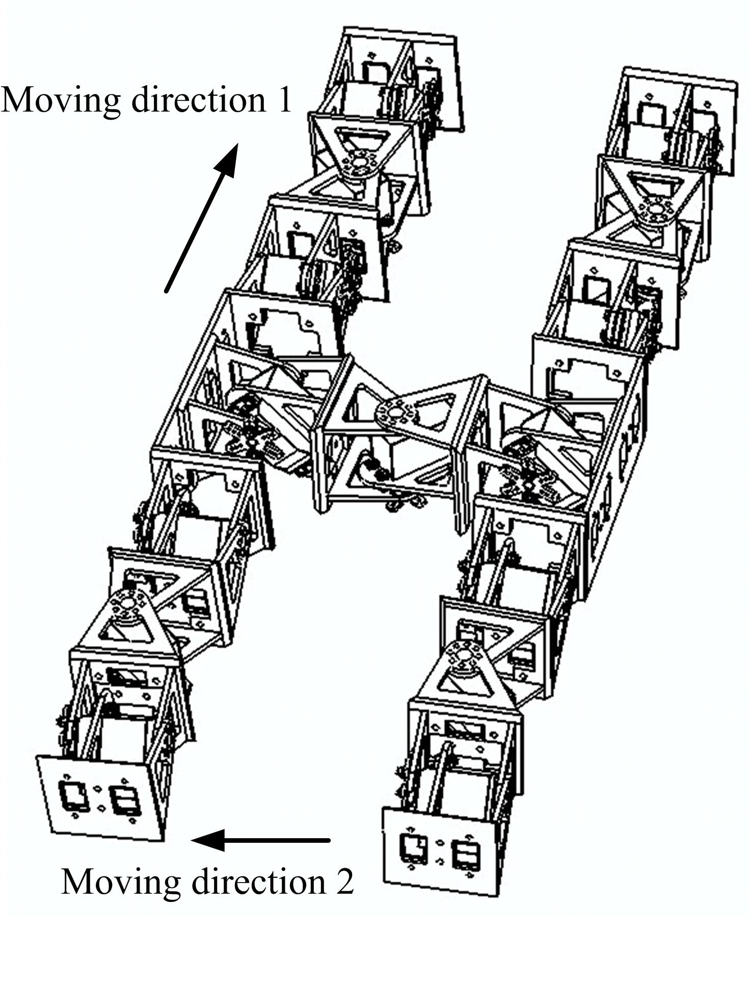
An even more interesting inspired robot is a four-legged robot, shown in Fig.9. We also call it an “H” structure. Actually, it consists of five chains, each of which has three cross-connected modules. The robot can imitate a dog’s movement in direction 1. In moving direction 2, the robot will move like a reptile. This prototype can also be considered as two biped robots in parallel. Very interesting research work can be done with this design.
We are also working on modular grasping, as shown in Fig. 10. Gionata Salvietti, a master student is working on it. The new information will come soon.
|
|
| Fig. 9 Four-legged Configurations | Fig. 10 Modular Grasping |
Other information
Copyright(C) Houxiang Zhang, All rights reserved
- The contents of this web site are with Copyright of Houxiang Zhang or a third party where contributors are indicated. You may view this site and its contents using your web browser. You may save or print an electronic copy of parts of this web site for your own information, research, or study. Permission must be sought for any other use.
- For the publication materials, although personal use is permitted, you are strongly suggested to obtain them directly from the publishers, such as IEEE. Permission to reprint/republish the material for advertising or promotional purposes or for creating new collective works for resale or redistribution to servers or lists, or to reuse any copyrighted component of the work in other works must be obtained from the publisher(e.g. the IEEE).