
 |  |
 DescriptionThis applet demonstrates interrupts an the on-chip timer
of the PIC16C84 microcontroller.
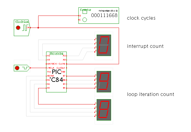
The circuit consists of the clock generator, microcontroller, and three (hexadecimal) seven-segment displays driven by the microcontroller ports A and B. The additional counter allows you to check the number of clock cycles between timer interrupts.
To watch the program execution or to edit the microcontroller program and data memories, select the popup-edit menu item. You can try changing the prescaler values in the OPTION register and setting a breakpoint in the InterruptHandler routine to better watch the program execution. The default values used in the program trigger an on-chip timer interrupt every 262144 (256*4*256) clock cycles.
The program running on the microcontroller is very simple (see the listing below). Program executes starts at address zero after a reset or power-up, where a goto instruction jumps to the main routine, called Start. This routine first calls two subroutines, InitPorts and InitTimer, to initialize the output ports and the on-chip timer module. Afterwards, it just enters an endless loop that increments a counter value and outputs the current counter value on port B, which in turn is displayed by the two hex-displays connected to the output port.
The InitPorts routine is also very simple. It first writes a value of 0x00 (all zeroes) into both port data registers, PORTA and PORTB. It then switches to memory bank 1 to address the port direction registers, and again writes all zeroes to both registers. This selects all pins of both ports (A4..A0 and B7..B0) as output pins. Finally, it switches back to memory bank 0.
The InitTimer routine switches back to memory bank 1 to select the processor control registers. It first writes the value 0x87 (0b10000111) to the option register, with the following effect:
 bit   value   name     meaning
   7       1   RBPU     port B pullups         0=enabled 1=disabled
   6       0   INTEDG   port B interrupt edge  0=falling 1=rising
   5       0   T0CS     timer clock-source     0=clkout  1=port A.4
   4       0   T0SE     timer clock-edge       0=rising  1=falling
   3       0   PSA      prescaler-assignment   0=timer   1=watchdog
   2       1   PS2      prescaler-value bit2   see datasheet
   1       1   PS1      prescaler-value bit1
   0       1   PS0      prescaler-value bit0
The net effect is that the prescaler register is assigned to the on-chip timer register, set to a 1:256 prescaling, and driven by the clkout pin. Therefore, the prescaler is incremented once for every instruction cycle. As every instruction cycle takes four input clock cycles, the timer register in incremented once every 1024 (4*256) input clock cycles. A timer interrupt is generated whenever the timer register overflows from value 0xff to 0x00, or every 256*1024 clock cycles.
Next, the InitTimer routine switches back to memory bank 0 and then clears the on-chip timer register TMR0. This also automatically clears the prescaler register, because this was assigned to the TMR0 by the previous write to the OPTION register. After this instruction has executed, the on-chip timer register is incremented once every (4*256) input clock cycles. Finally, the value 0xA0 (0b1010000) written to the interrupt control register INTCON enables the on-chip timer overflow interrupt (bit 5) and the global interrupt flag (bit 7).
Whenever the on-chip timer overflows, the T0IF flag is set in the interrupt control register INTCON. Because the previous setup (in InitTimer) has enabled timer interrupts, the processor fetches its next instruction from the (hardcoded) address 4, which contains a goto to our InterruptHandler routine. This in turn simply increments the N_INTERRUPTS counter (at memory location 11), and outputs the four lower bits of the counter value on the four lower bits of port A. Again, the hex-display connected to the port allows you to watch the value during the simulation. Next, the interrupt handler routine clears the INTCON register, and then re-enables the timer interrupt. The final return-from-interrupt instruction retfie automatically re-enables the global interrupt flag, and the program resumes in the main counter loop.
; TITLE           "PIC16F84 timer interrupts demo"
; SUBTITLE        "FNH 21.10.2005"
; Processor       16F84
; Radix           DEC
; EXPAND
; include         "p16c84.inc"


N_ITERATIONS	equ 	0x10
N_INTERRUPTS	equ	0x11

;
; program execution in the PIC16 architecture (after reset and power-up)
; starts at adress 0, while the interrupt routine starts at address 4.
; We put jump instructions to our main program (Start) and our timer
; interrupt handler (InterruptHandler) there.
;

	org	0
	goto	Start

	org	4
	goto	InterruptHandler


;
; main program: first initialize the timer and the ports.
; Then enter an endless loop, which increments the loop counter and
; outputs the counter value on port B.
;
	org	10
Start:
	call	InitPorts
	call	InitTimer

Loop:
	incf	N_ITERATIONS	; count loop iterations
	movf	N_ITERATIONS,0	; output
	movwf	PORTB		; on port B
	goto	Loop

;
; make port B all outputs.
; We use ports A3..A0 to output the timer interrupt counter,
; and ports B7..B0 to output the normal program loop counter.
;
InitPorts:
	movlw	0x00		; all zeroes
	movwf   PORTB		;
	movwf	PORTA		;
        bsf     STATUS, RP0	; bank 1
	clrf    TRISA 		; all outputs
	clrf    TRISB 		; all outputs
        bcf     STATUS, RP0	; bank 0 again
	return

;
; enable the on-chip timer and timer interrupts
;
InitTimer:
        bsf     STATUS, RP0	; bank 1
	movlw   B'10000111'     ; rtcc inc = tcylc/256 = tclk/(4*256)
	movwf   OPTION_REG      ;
        bcf     STATUS, RP0	; bank 0

	clrf    TMR0            ; reset timer (and prescaler!)
	movlw   B'10100000'     ; enable timer interrupt and GIE
	movwf   INTCON          ;
	return

;
; interrupt-handler. We don't check for the interrupt source,
; because only the timer-interrupt is enabled.
;
InterruptHandler:
	; btfsc   INTCON,T0IF	; was this a rtcc interrupt?

	incf	N_INTERRUPTS	; count this interrupt
	movf	N_INTERRUPTS,0	;
	andlw	0x0f		; mask lower four bits
	movwf	PORTA		; and output them on port A

	clrf	INTCON		; clear all interrupts
	bsf	INTCON,T0IE	; enable RTIE again
	retfie			; return (enables GIE again)

	end
Run the applet | Run the editor (via Webstart)