
 |  |
 DescriptionThis applet demonstrates the parity modes of the
USART 8251
universal synchronous and asynchronous receiver and transmitter.
For an overview and register description of the USART chip,
please visit the 8251 overview applet page.
Most RS-232 receivers and transmitters include the option to calculate and append a parity bit to each sent data character; usually, either even or odd parity can be selected. If the receiver is setup to the same parity mode as the transmitter, all signle-bit errors (and half of the multi-bit errors) in the data-stream can be detected. Naturally, automatic error-correction is not possible with a simple parity code; if necessary a better ECC code or a handshaking protocol for data retransmission must be used on top of the raw RS-232 encoding.
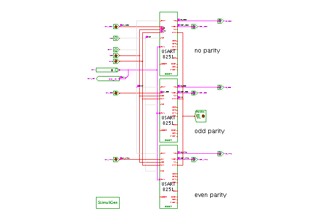
As you can see, the circuit shown in the applet includes a total of three 8251 chips. The TXC inputs of all three chips are driven by the same clock generator which is set to a clock period of 1.6667 msec or 600 baud. The nCTS (clear to send) inputs of all chips are tied to ground to enable the transmitters. A stimuli generator component is used to automatically initialize all three USARTs for transmission at the start of the simulation. However, different communication parameters are selected for the three USART chips:
After the initialization sequence, the stimuli generator component drives the databus with a few selected 8-bit characters and then enables the nWR signals of all three USARTs simultanously. Therefore, all three 8251 chips start to transmit the same characters at the same time, but with different parity modes. The first few transmitted characters are selected because they are easy to recognize via their bit-pattern in the RS-232 encoding:
0x55 0xAA 0x33 0x00 0x01 0x02 0x03 0x00Afterwards, the string "Hello, world!" is transmitted:
0x48 0x65 0x6c 0x6c 0x6f 0x2c 0x20 ...Note that the stimuli-generator pauses the simulation after its automatic sequence has finished. This should take at most a few seconds.
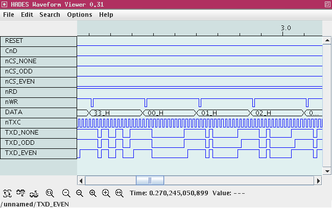
When the automatic sequence has finished, you should look at the signal waveforms and compare the RS-232 datastreams and check the different parity modes. Just click the repaint button in the waveform viewer to update the waveforms, and use the zoom buttons or the zoom-region option to enlarge the areas of interest. The screenshot below shows example waveforms during the first block of transmitted characters.

To explore the circuit, just continue the simulation via clicking the "run" button (play) in the simulator control panel. You can now use the DATA input switch and the nWR write-enable switch to transmit other data characters via the three USART chips. Use the nCS lines (nCS_NONE, nCS_ODD, nCS_EVEN) to enable one, two, or all three of the chips. You can also type the following bindkeys to control the applet: 'r' for nRD, 'w' for nWR, 'x' for RESET, 'n' for nCS_NONE, 'o' for nCS_ODD, and 'e' for nCS_EVEN.
Run the applet | Run the editor (via Webstart)