
 |  |
 Description
This applet is meant as an introduction to switch-level simulation.
It demonstrates a basic interactive switch and a simple lightbulb.
While the circuits shown in this and the following applets
are very simple, the underlying simulation algorithm is rather complex.
Please check the explanation at the end of this page
for an overview of the switch-level simulaton algorithm used in Hades.
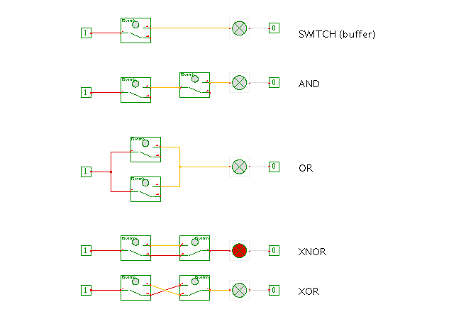
Please use mouse-clicks to toggle the state of the switches, because bindkeys are not yet implemented for them. The state of the switch is indicated by the orientation of the actual switch contact, and also by the color of the small circle inside the switch symbol.
Each switch has one common connection (port A) and both a normally-open (port A1) and a normally-closed (port A0) connection. When the switch state is 'off', the ports A and A0 are connected, while A1 is disconnected. When you press the switch, the state changes to 'on', and the ports A and A1 are connected, while A0 is left unconnected.
The first circuit (topmost) demonstrates a single switch connected to a lightbulb. As you can see, the Constant1 and Constant0 simulation components have been used to model the supply voltage (think of Constant1 as VCC +5 volts and Constant0 as GND or zero volts). Therefore, the lightbulb will be activated as soon as you press the switch, because there is then a conducting path from VCC throught the lightbulb to GND.
The next two circuits demonstrate the logical AND, realized as the series-connection of two switches, and the logical OR, realized via the parallel-connection of two switches.
The two circuits at the bottom demonstrate the use of the 'changeover'-type switches with both their normally-closed an normally-open contacts to realize the XOR and XNOR functions.
On the other hand, using a fully separate simulation engine and algorithm would imply that none of the existing simulation components could be re-used for the switch-level simulations. Therefore, Hades uses a slightly modified algorithm for switch-level simulation which allows us to integrate the standard simulation components with switch-level simulation components. At the core of the modified simulation algorithm lies a new subtype (class hades.signals.SignalStdlogicSwitched) of the standard signal type (class hades.signals.SignalStdlogic1164). Simulation components that require switch-level behaviour are tagged as such via implementing the interface hades.simulator.GenericSwitch. All those simulation components are currently packaged into the package hades.models.switched, but this is just a convention.
The main trick that enables switch-level simulation is the evaluate method of class SignalStdlogicSwitched. It will first collect all 'direct' drivers connected to the signal itself and apply the std_logic_1164 resolution function to calculate its new value. However, it will next check whether any switch-level components are connected to it, and ask that component for all other signals currently switched onto itself. For each such signal, its 'direct' drivers are included in turn in the resolution function, and any switched signals are recursively visited. Finally, the resulting new logic value is propagated to all 'direct' receivers, as well as to all indirect (switched) signals visited during the previous phase. A hashtable ensures that every signal is visited at most once during one evaluation phase, which also catches cyclic signal structures.
During the interactive schematics entry of a new switch-level design, the editor will create new signals depending on the type information provided by the simulation component in question. For standard simulation components, this will be SignalStdlogic1164, and the editor will not change this during an edit operation. Therefore, all simulation components that require switch-level behaviour are expected (required) to themselves check that all their switched ports are actually connected to SignalStdLogicSwitched signals, usually from within their elaborate and evaluate methods. If necessary, a normal signal must be converted to a switched signal before the simulation starts. A corresponding utility method is provided by class SignalStdLogicSwitched.
Please remember the following three issues when designing your own switch-level circuits in Hades: