TAMS / Java / Hades / applets (print version): contents | previous | nextUsing glow mode
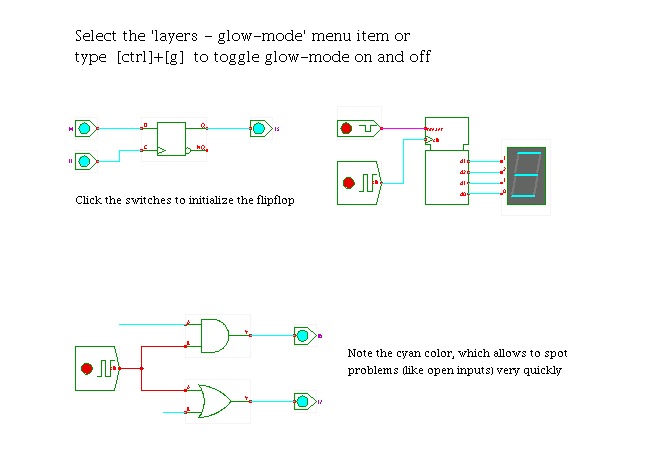 DescriptionPerhaps the most important visualization aid in
the Hades simulation framework is glow mode,
where different colors are used to show the current values
of all signals (wires) in the circuit schematic.
Naturally, this technique is used by several other simulators as well.
When glow-mode is enabled,
the signal wires are drawn in a color corresponding to the current
logical value on that signal at the given simulation time.
The schematic is updated periodically during the simulation.
For example, signals of type SignalStdLogic1164 use a color encoding
that allows to distinguish the logical values (e.g. 0 or 1) at a glance.
As 'aggressive' colors like cyan and magenta are used to indicate
undefined or illegal logic values, problems in a circuit can be
spotted very quickly - see the open input on the AND and OR gates.
One of the next applets
contains a detailed explanation
of the std_logic multilevel logic system and the color encoding
of the nine logic values.
Similarly, signals of type SignalStdLogicVector use different colors
to indicate the current numerical value of the corresponding bus.
The colors can be changed via properties in the Hades configuration files.
User-defined signal classes are free to define their own color encoding.
On the other hand, with glow-mode off,
all signal wires are drawn in the same standard color (currently, blue).
As the simulator doesn't need to update the signal wires,
the simulation can run faster when glow-mode is off.
Also, the uniform blue color can be better when printing the
schematics, especially on black and white printers.
To toggle glow mode, either select the corresponding (popup) menu item
in the editor or viewer, or simply press the 'control+g' bindkey
(when the schematics editor has the keyboard focus).
In the editor GUI, the menu item is in the 'layers' menu,
while the applet (=viewer) uses the 'view' submenu of the popup-menu.
The schematics will be updated on the next periodic redraw,
typically within a fraction of a second.
Note that very short pulses on a wire might not show up at all
if they are over before the next redraw operation begins.
You can try to change the default repaint frequency
via the menu items in 'select repaint frequency...' submenu
of the view menu. As redrawing is very compute intensive,
selecting high repaint frequencies may reduce the simulation speed
(it can even lead to crashes of the Java virtual machine).
Run the applet | Run the editor (via Webstart)
DescriptionPerhaps the most important visualization aid in
the Hades simulation framework is glow mode,
where different colors are used to show the current values
of all signals (wires) in the circuit schematic.
Naturally, this technique is used by several other simulators as well.
When glow-mode is enabled,
the signal wires are drawn in a color corresponding to the current
logical value on that signal at the given simulation time.
The schematic is updated periodically during the simulation.
For example, signals of type SignalStdLogic1164 use a color encoding
that allows to distinguish the logical values (e.g. 0 or 1) at a glance.
As 'aggressive' colors like cyan and magenta are used to indicate
undefined or illegal logic values, problems in a circuit can be
spotted very quickly - see the open input on the AND and OR gates.
One of the next applets
contains a detailed explanation
of the std_logic multilevel logic system and the color encoding
of the nine logic values.
Similarly, signals of type SignalStdLogicVector use different colors
to indicate the current numerical value of the corresponding bus.
The colors can be changed via properties in the Hades configuration files.
User-defined signal classes are free to define their own color encoding.
On the other hand, with glow-mode off,
all signal wires are drawn in the same standard color (currently, blue).
As the simulator doesn't need to update the signal wires,
the simulation can run faster when glow-mode is off.
Also, the uniform blue color can be better when printing the
schematics, especially on black and white printers.
To toggle glow mode, either select the corresponding (popup) menu item
in the editor or viewer, or simply press the 'control+g' bindkey
(when the schematics editor has the keyboard focus).
In the editor GUI, the menu item is in the 'layers' menu,
while the applet (=viewer) uses the 'view' submenu of the popup-menu.
The schematics will be updated on the next periodic redraw,
typically within a fraction of a second.
Note that very short pulses on a wire might not show up at all
if they are over before the next redraw operation begins.
You can try to change the default repaint frequency
via the menu items in 'select repaint frequency...' submenu
of the view menu. As redrawing is very compute intensive,
selecting high repaint frequencies may reduce the simulation speed
(it can even lead to crashes of the Java virtual machine).
Run the applet | Run the editor (via Webstart)
Impressum | 24.11.06
http://tams.informatik.uni-hamburg.de/applets/hades/webdemos/00-intro/00-welcome/glowmode_print.html
