TAMS / Java / Hades / applets (print version): contents | previous | nextAnimated 2 Floor Elevator
 Description
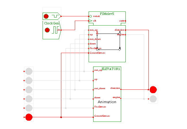
This applet demonstrates the 2 floor elevator controller,
used as an example for state-machine design in many textbooks.
To motivate and illustrate the elevator controller design,
the applet contains a special simulation component that visualizes
the elevator and its internal/external control button.
Use the popup-menu ('edit') on the elevator component
to open the window with the elevator visualization.
Press any external and/or internal buttons on first and ground floor
and watch the behavior of the elevator controller.
You can also open the state-machine editor to watch and edit
the controller.
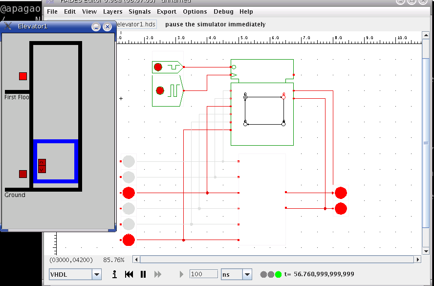
The following image shows a screenshot of the applet with
both the elevator animation and the state-machine editor open
at the same time:
 Elevator has four buttons. Two external buttons and two internal
buttons (in the elevator car).
In addition, there are two floor level sensors. When the
elevator is on the ground floor, the ground sensor is ON. If the
elevator moves up, the ground sensor is OFF, and the first level sensor
will be switched ON when the elevator arrives on the first floor.
The engine and direction are elevator inputs.
Inputs:
engine: ON and OFF
direction: move up (ON), move down (OFF)
Outputs:
FirstSensor: ON if the elevator is on first floor, otherwise OFF
GroundSensor: ON if the elevator is on ground, otherwise OFF
out_up and out_down: External buttons. Switch ON if pressed, and stay on until the elevator arrives in correct floor.
up and out: Internal buttons. Switch ON if pressed, and stay on until the elevator arrives in correct floor.
Component written by Ulisses Chippe, Giliardo Freitas and
Ricardo Ferreira, DPI, Universidade Federal Vicosa, Brazil, cacau@dpi.ufv.br
To edit the state-machine, activate the popup-menu on the
FSM symbol and select the edit menu item.
This opens the editor window for the FSM,
which uses a mode-oriented user-interface.
- move-mode: Click-and-drag any one of the state
symbols (circles) to a new location on the editor canvas.
The currently selected state is highlighted in red.
Use the textfield on the lower left to set the name
of the selected state.
To change the output values for Moore-type outputs in the selected state,
first select that output in the list on the lower left and then
select the new output-value (0 or 1) in the radio-button on the
bottom.
- state-mode: Click the mouse to create a new state
and set its name and the default output values via the GUI controls
on the lower left part of the editor window.
- transition-mode: To create a new transition between states,
first click of the initial state, then on the final state.
Enter the logical condition that activates the transition
in the textfield on the lower left, e.g. "*" for an always active
transition, or "A&B" for a transition that is only active if
the "A" and "B" inputs are both active (1).
- comment-mode: Click the mouse to specify the position for
a new text comment on the editor canvas; next enter the comment
into the text-area in the lower left part of the editor window
and finally press "apply" to create the comment.
- delete-mode: Click the mouse to delete a state,
transition, or comment.
- starting state-mode: Click the mouse on a state symbol
to select that state as the initial starting-state of the FSM.
- Click the test FSM button to run a simple selftest that
checks for each state whether transitions are active for any
combination of inputs.
- Use the load and save as operations to load or save
the FSM design file.
Run the applet | Run the editor (via Webstart)
Impressum | 24.11.06
http://tams.informatik.uni-hamburg.de/applets/hades/webdemos/95-dpi/elevator2floors/elevator1_print.html


 Description
This applet demonstrates the 2 floor elevator controller,
used as an example for state-machine design in many textbooks.
To motivate and illustrate the elevator controller design,
the applet contains a special simulation component that visualizes
the elevator and its internal/external control button.
Use the popup-menu ('edit') on the elevator component
to open the window with the elevator visualization.
Press any external and/or internal buttons on first and ground floor
and watch the behavior of the elevator controller.
You can also open the state-machine editor to watch and edit
the controller.
The following image shows a screenshot of the applet with
both the elevator animation and the state-machine editor open
at the same time:
 Elevator has four buttons. Two external buttons and two internal
buttons (in the elevator car).
In addition, there are two floor level sensors. When the
elevator is on the ground floor, the ground sensor is ON. If the
elevator moves up, the ground sensor is OFF, and the first level sensor
will be switched ON when the elevator arrives on the first floor.
The engine and direction are elevator inputs.
Inputs:
engine: ON and OFF
direction: move up (ON), move down (OFF)
Outputs:
FirstSensor: ON if the elevator is on first floor, otherwise OFF
GroundSensor: ON if the elevator is on ground, otherwise OFF
out_up and out_down: External buttons. Switch ON if pressed, and stay on until the elevator arrives in correct floor.
up and out: Internal buttons. Switch ON if pressed, and stay on until the elevator arrives in correct floor.
Component written by Ulisses Chippe, Giliardo Freitas and
Ricardo Ferreira, DPI, Universidade Federal Vicosa, Brazil, cacau@dpi.ufv.br
To edit the state-machine, activate the popup-menu on the
FSM symbol and select the edit menu item.
This opens the editor window for the FSM,
which uses a mode-oriented user-interface.