
 |  |
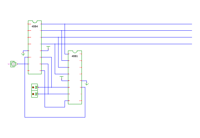
 DescriptionThis circuit demonstrates the test-input of the i4004
microprocessor.
While the i4004 had no support for interrupts,
an extra input pin called test
and a corresponding jump-instruction were provided by the processor.
The circuit shown here consists of the i4004 microprocessor, one i4001 ROM chip with its I/O ports configured as output ports and connected to a hex-display, and a single input switch conntected to the processor's text input.
Wait until the simulation has started, then start clicking the input switch. The software running on the processor will count your clicks and display the current counter-value (4-bit) on the hex-display. If necessary, switch glow-mode off to reduce the number of repaints to speed up the simulation.
The program used in this applet basically consists of a single endless loop: jmp_test.asm. At the beginning of each loop iteration, the current value from register R0 is transfered to the I/O-ports of the ROM-chip, (and displayed by the hex-display). Next the program calls the subroutine checkTest. If the subroutine returns the value 1, the counter variable R0 is incremented, otherwise the next loop iteration is started right away.
The remaining logic in subroutine checkTest and newTest ensures that the test-switch is released before the counter variable is next incremented (input switch debouncing).
; jmp_test.asm
; increase on test
	FIM R0R1, 0      ; initialize: R0=0, R1=0
begin:
	JMS display      ; display current value of R0 on ROM I/O pins

	JMS checkTest    ; check test-signal
	JCN Z, begin     ; no test, next iteration

	INC R0           ; increase Register 0
	LDM 1            ; 1 into accumulator
	XCH R1           ; store 1 in Register 1
	JUN begin        ; next iteration


; subroutine to check the test input
;
checkTest:
	JCN T, test      ; conditional jump if test
	LDM 0            ; 0 into accumulator
	XCH R1           ; store 0 in Register 1
	BBL 0            ; return zero: no inc
test:
	LD R1            ; load Register 1
	JCN Z, newTest   ; signal is new
	BBL 0            ; inc
newTest:
	BBL 1            ; no inc


; copy contents of R1 onto ROM output port pins
;
display:
	FIM R2R3, 0
	SRC R2R3
	LD R0
	WRR		 ; write to ROM output pins
	BBL 0
See also:
Run the applet | Run the editor (via Webstart)