
 |  |
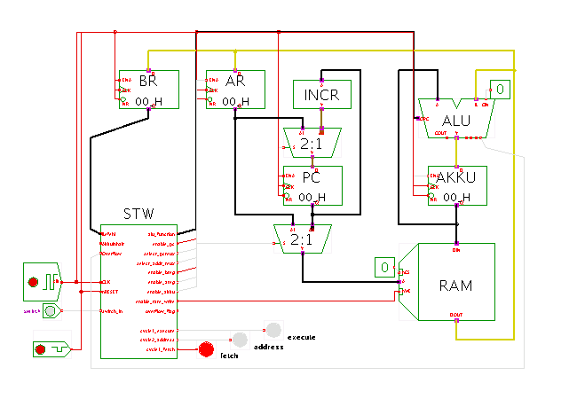
 DescriptionAnother demonstration of the PRIMA processor
with the following program:
# simple PRIMA program to demonstrate external (SW) input.
# The program initializes the variable count (at RAM location 24)
# then enters a loop to increment / decrement the count variable
# depending on the current value of the input switch SW.
#
# .program
0     14      # LD 0      akku = 0
1     0       #           dummy
2     72      # ST 24     count = 0
3     24      #

# .loop
4     145     # BSW       sw == 1 ?
5     14      #


# .decrement
6     09      # LD 24     akku = count
7     24      #
8     12      # SB1       akku = akku - 1
9     0       #
10    72      # ST 24     count = akku
11    24      #
12    128     # BR 4      goto loop
13    4       #


# .increment
14    09      # LD 24
15    24      #
16    10      # AD1
17     0      #
18    72      # ST
19    24      #
20    128     # BR
21    4       #

#
# .data
24    0       # Variable c
# .end
Depending on the external input switch, the variable at memory address 24 (or 0x18) is incremented or decremented.
The program loop, which starts at address 4, uses the BSW (branch-if-switch) instruction to read the external switch input and jumps to address 14 if the switch is set. Otherwise, the program continues at address 6, reads the counter variable from the memory, decrements it, and stores it back. The corresponding part of the loop starting at address 14 increments the counter variable.
Open the memory editor window (popup-menu, edit-component) to watch the execution of the program. You might also want to change the clock frequency to speed-up the execution a bit.
Note: to keep the schematics as simple as possible, this applet again uses the simplified datapath with 8-bit ALU and 8-bit accumulator register. Also, neither the accumulator output nor the carry-out output from the ALU are connected to the control unit. This does no harm, because the above program only uses the BSW (branch-if-switch) instruction, but none of the arithmetic comparison instructions.
Run the applet | Run the editor (via Webstart)