
 |  |
 Description
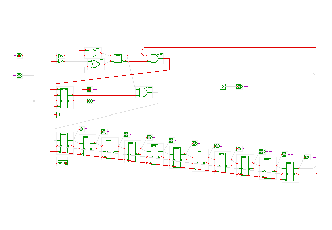
The controller state-machine for the RS-232 receiver.
The circuit shown here is based on a state-machine with one-hot encoding. The DFFRS-type flipflop on the left (middle height) of the schematics is used to encode the 'idle' state of the controller. It is set while the controller waits for the start of the next transmission. As such, the 'idle' and 'busy' outputs of the controller are directly driven by the positive and negated outputs of the DFFRS flipflop.
The gates and SR-type flipflop on the upper part of the circuit are used to detect the start-bit on the RX input signal. The AND-gate in front of the set-input of the SR flipflop ensures that a low value on the RX input line sets the flipflop when the controller is in the 'idle' state. The SR-flipflop is reset in the 'latch' state of the controller, indicated by a high-value of the next-to-last (bottom-right) flipflop. The SR-flipflop is also reset by the global power-on reset.
Once the SR-flipflop is set, the 'idle' flipflop will be reset on the next rising-edge of the clock. At the same time, the 'D0' state flipflop (leftmost on the bottom row of flipflops) will be set. Due to the shift-register structure of the remaining D-type flipflops, the 'D1', ... 'D7', 'PARITY', 'LATCH', and 'STROBE' flipflops will be set in sequence during the following clock cycles. Due to the one-hot encoding style, each of the flipflop outputs is directly connected to the corresponding output of the controller. The 'latch' and 'strobe' outputs are used in the top-level receiver circuit to latch the contents of the input shift-register to the output-buffer register, and to signal that a new characters has been received to the external logic via the 'strobe' pulse.
While the controller provides an 'error' output pin, this is currently hardwired to a low value. A better implementation of the controller would check for protocol errors and indicate these via the 'error' output.
A typical UART controller allows the user to select the baud-rate, number of data-bits, parity mode (none, even, odd), and the number of stop bits. It should be obvious how such parameters could be added to the controller, e.g. by bypassing the D7 and PARITY states when seven data bits and no parity are selected.
Run the applet | Run the editor (via Webstart)