
 |  |
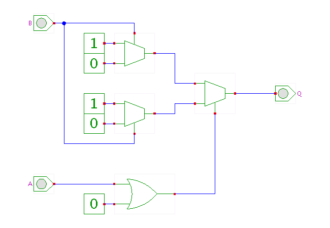
 DescriptionThe ACT1 basic logic cell configured to implement
a two-input XOR gate.
The A is connected to the second-level multiplexer and controls which first-level multiplexer drives the output Q. The B is connected to the control inputs of both first-level multiplexers, whose inputs are tied to low and high level to implement the XOR function of A and B.
If a third input signal C were available in both its non-inverted and its inverted form /C, this signal could be connected to the first-level multiplexer data-inputs in the obvious manner to construct a three-input XOR (parity/adder) gate.
Click the input switches or type the 'a' and 'b' bindkeys to control the applet.
Run the applet | Run the editor (via Webstart)