TAMS / Java / Hades / applets (print version): contents | previous | nextLFSR based testbench with generator and analyzer
 DescriptionA demonstration of
LFSR-based circuit selftest.
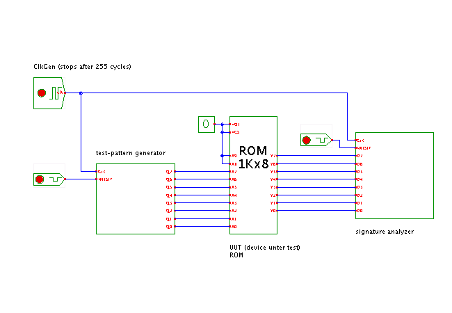
The circuit consists of three main parts:
- the linear-feedback shift-register on the left
is used as a test pattern generator.
- the unit under test, whose function is to be tested.
For demonstration purposes, a single ROM is used in the applet,
because the ROM contents can be changed easily via the memory editor.
- the parallel-input linear-feedback shift-register on the right
is used as a signature analysis register that
reads and accumulates the output values of the UUT.
Phase 1 (reset):
For the whole selftest, all parts of the circuit are first reset.
This sets well-defined initial values for the LFSR generator
and signature analysis registers.
Phase 2 (pattern generation and analysis):
Next, the circuit is driven at full speed by the clock signal
for a sufficiently large number of clock cycles.
In the applet, a special clock generator is used that automatically
stops after a preset number of clock cycles (here 255).
As an 8-bit pattern generator (with maximum period) is used,
this ensures that all possible input combinations are generated
for the UUT circuit.
Phase 3 (signature read-out):
After the test has finished, the final signature value is read out
from the analysis register. (Use the popup-edit operation to open
the property sheet for the signature analysis register).
Usage:
Once the applet has loaded, let the simulation run until the
clock-generator stops.
Now open the property-sheet (popup-menu, edit-component)
of the LFSR signature analyzer register (on the right)
and write-down the signature value.
Close the property-sheet.
Now open the property-sheet of the RAM component and change
the memory contents.
Re-run the simulation, open the property-sheet of the signature register
again, and read the final analyzer register value.
The signature will differ from the expected signature of the
previous run with very high probability.
Therefore, a simple comparison of the final signature value
with the expected signature value allows to detect whether the
memory works and the memory contents are intact.
(You can try to find new memory data that will result in the
original signature value, but be warned that this is very difficult.
You will have to close the property-sheet of the signature register
between simulation runs, because the GUI is not automatically updated
during the simulation.)
To keet the circuit simple and the simulation runtime short,
only the lower eight address inputs have been used in the applet.
Therefore, changes in the memory data above address 255 will not be
detected by this circuit.
One of the main advantages of LFSR-based selftest is that the circuit
can be tested at full clock-rates without the need for external equipment.
Therefore, testing with very many input patterns is possible,
for very good error coverage.
For example, running a selftest for 1 second at 100 MHz clock rate
implies testing of 100 million test-patterns.
Run the applet | Run the editor (via Webstart)
Impressum | 24.11.06
http://tams.informatik.uni-hamburg.de/applets/hades/webdemos/35-selftest/30-lfsr/testbench_print.html


 DescriptionA demonstration of
LFSR-based circuit selftest.
The circuit consists of three main parts: