
 |  |
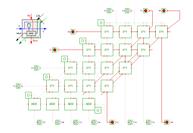
 DescriptionThis circuit demonstrates the highly regular structure
of an integer array multiplier.
The multiplier used in the applet takes two 4-bit inputs X and Y
and generates the 8-bit product value P.
Each multiplier cell uses a standard AND-gate to calculate
the 1-bit product of its Xi and Yi inputs,
and a standard full adder to sum the partial products.
(Click the input switches, or type the bindkeys '1'..'4' to control the X0..X3 inputs and 'a','s','d','f' to control the Y0..Y3 inputs.)
The layout of the cells in the schematics is based on the usual pen-and-paper multiplication algorithm with the typical orientation of the partial products. In general, an N-bit array multiplier consists of N*N single-bit multiplier cells and one final row of adder cells.
Naturally, it is more space efficient to use a rectangular orientation of the cells for an actual VLSI implementation. Due to the regularity of the structure, it is feasible to generate the layout of such multipliers automatically for a given integrated circuit technology. While higher speed multipliers are possible, the dense layout of the multiplier array will often compensate any speed advantage of more complex circuits built from standard cells, unless expensive and tedious manual layout is used for the more complex multipliers.
Run the applet | Run the editor (via Webstart)