
 |  |
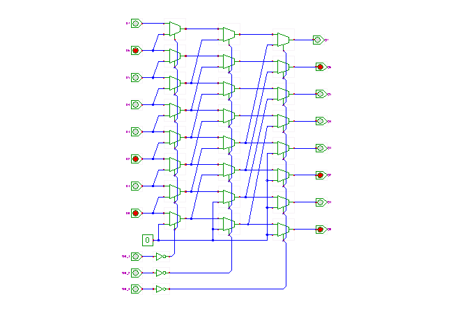
 DescriptionThis applet demonstrates a multiplexer-based 8-bit barrel-shifter.
The circuit allows shifting the input data word left,
where the amount of shifting is selected via the control inputs.
Several microprocessors include barrel-shifters as part of their ALUs
to provide fast shift (and rotate) operations.
The circuit shown in the applet consists of three stages of 2:1 multiplexers, with one multiplexer per bit of the input data (here 8). When all multiplexer select inputs are inactive (low), the input data passes straight through the cascade of the multiplexers and the output data (Q7..Q0) is equal to the input data (D7..D0). When enabled via the SHL_1 input, the first stage of multiplexers performs a shift-left by one bit operation, due the their interconnection to the next-lower input. A low input value (0) is used for the least significant bit, so that the shifter output becomes (Q6..Q1 0).
Similarly, the second stage of multiplexers performs a shift-left by two bits when enabled via the SHL_2 control signal. Note that the corresponding multiplexer inputs are connected to their second next-lower input, and two zeroes are required for the lowest bits. Finally, the third stage of multiplexers performs a shift-left by four bits, with four zero bits filled into the lowest bits.
Due to the cascade of three stages, all three shift operations (by one bit, by two bits, and by four bits) can be activated independently from each other. For example, when both SHL_1 and SHL_4 are activated, the shifter performs a shift-left by five bits. The generalization to higher word-width (e.g. 64 bits) and higher number of stages (e.g. 8) should be obvious, as should the construction of shift-right or rotate operators.
Run the applet | Run the editor (via Webstart)