
 |  |
 Description
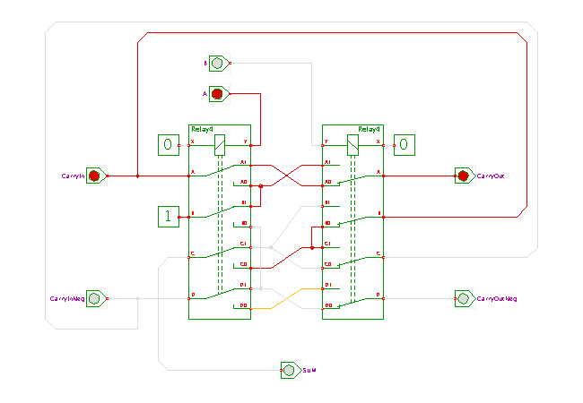
This circuit demonstrates the (rather clever) full-adder circuit
designed by Konrad Zuse for his Z3 relay-based computer.
The Z3, built in Berlin around 1941 and later destroyed during World War II,
is considered the first fully operational programmable
digital computer in history.
Unfortunately, the machine wasn't widely known at the time,
and the designers of the first electronic computers in the US and UK
had to re-discover many of the groundbreaking inventions of the Z3
(e.g., the use of binary and floating-point arithmetic).
It seems that the adder circuits shown here was already used earlier
in Zuse's Z1, a mechanical machine based on levers and sliders,
built back in 1936 when he was still a student.
Many thanks to Prof. Harry Porter of Portland State University
for pointing out Zuse's adder design!
You can visit his website for photos of Prof. Porter's own
8-bit relay
based computer.
A detailed description of the computer designs by Konrad Zuse can be found in the book by Prof. Raul. Rojas, Die Rechenmaschinen von Konrad Zuse, Springer Verlag, Berlin, ISBN 3-540-63461-4, 1998 (in German). The book also documents the unbelievable story of Zuse's patent application for the digital computer being rejected by the German patent office due to reasons of "niedrige Erfindungshöhe" (not worth patenting)...
The main feature of the adder circuit is the use of a dual-rail encoded carry-signal. That is, both the positive and the negated polarity of the carry-signal are inputs to the circuit, and both the positive and the negated polarity of the resulting carry-output are propagated by the adder. Note that only two relays (with four crossover switches each) are required for a one-bit full-adder.
Note that the carry-signal is propagated instantly after the input values A and B and the (dual-rail encoded) Carry input are applied to the circuit. Therefore, an n-bit adder is almost as fast as a 1-bit adder, because the propagation of the electrical signals is much faster than the switching time of the relays.
One additional relay, which is not included in the schematics, will be necessary to generate the inverted CarryInputNeg signal from the CarryIn signal for the first level adder.
Click the input switches or type the ('a','b','c' and 'd') bindkeys to control the circuit and watch the behavior. For correct operation of the circuit, the CarryIn and CarryInNeg inputs must have opposite polarity!
Run the applet | Run the editor (via Webstart)