
 |  |
 Description
This applet demonstrates the Hades 'relay' and 'lightbulb' simulation
components.
Click the input switches or type the 'a', 'b', ..., 'e' bindkeys to control the simulation and watch the circuit behaviour.
A relay consists of a set of mechanical switches connected to a common lever which moves inside a magnetic coil. The elasticity of the contacts inside the switches or a separate spring mechanism ensure that the contacts return to a default position when no current is applied to the magnetic coil. When a sufficient voltage is applied to the coil, the lever inside the coil moves and all switches of the relay toggle from their 'normal' position to their 'active' position. For best compatibility with common semiconductor circuits, most currently available relays are operated with coil voltages of about 3.3 volts or 5 volts. (Another common operating voltage are the 12 volts or 24 volts used in car electrics.) However, the switches are usually specified for much higher voltages, often 220 volts or higher. Not surprisingly then, a typical use of relays is to switch high-voltage loads (like motors) from low-voltage semiconductor circuits.
Many relays provide 'changeover' type switches, each with a common connection and one 'normally closed' and another 'normally open' connection. The 'normally closed' connection is closed when the relay is inactive, while the 'normally open' connection is closed when the relay is activated by a current through its coil. Relays for special purposes often include only those connections required; for example, many simple relays intended to simply switch-on a high-voltage load only include a single 'normally open' switch.
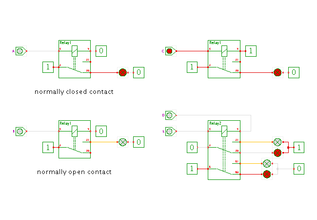
At the moment, three types of relays are included in the Hades hades.models.switched package. While the Relay1 simulation model provides a single 'changeover' type switch, the Relay2 and Relay4 provide two and four separate 'changeover' switches, respectively. As seen in the applet, the 'normally closed' connection is between the 'A' and 'A0' ports, while the 'normally open' connection is between 'A' and 'A1'; similar for B-B0 (normally closed) and B-B1, etc.
In the Hades simulation model, the connections to the coils are named 'X' and 'Y' on each relay, and the relay is activated when one of the coil connections is at logical 0 level, while the opposite coil connection is at logical 1. While the simulation model is based on the std_logic_1164 multilevel logic system, and therefore compatible with all other simulation models in Hades, the relay does ignore undefined ('U'), unknown ('X'), or weak ('Z', 'W', 'L', 'H') inputs to its coil. The relay will simply be inactive unless strong '0' and '1' values are applied to its coil. This makes the relay-based circuits much easier to understand, and it allows us to model standard relay-circuits without including extra reset logic.
The lightbulb simulation component (hades.models.switched.Bulb) is similar to the relay coil. It is activated by opposite strong (0/1) values on its ports, and ignores undefined or weak inputs. An active bulb is colored red, while the inactive (dark) bulb is gray.
The circuit shown in the upper left part of the circuit demonstrates the 'normally closed' contact. The right connection of the relay coil is connected to ground (logical 0), so that the relay is activated when a logical 1 (supply voltage) is applied to the left connection of the coil. The circuit in the lower left demonstrates the 'normally open' contact.
The circuit in the lower right demonstrates that the relay coil is activated independent of polarity: the relay is activated by both the D=0 and E=1 or D=1 and E=0.
Run the applet | Run the editor (via Webstart)