
 |  |
 Description
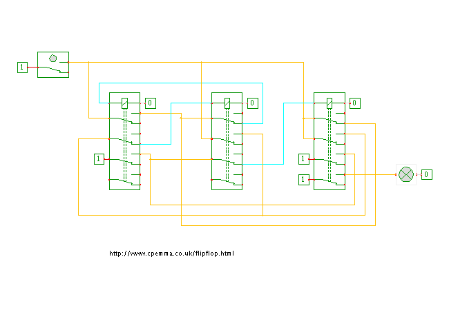
This applet demonstrates another relay toggle-flipflop.
The circuit shown here is a redrawn and interactive version
of the toggle flipflop shown and described on the
Flip Flop Fans
webpage, which in turn references the following posting on the
diyAudio forum by a user called roger-k.
Unlike the (hazard-prone) version shown in the
previous applet,
this circuit should actually work with most types of relays.
Click the input switch or type the 'c' bindkey to control the circuit and watch the resulting behavior. The following explanation is cited from the Flip Flop Fans website: Start-up is with everything off. When the button S1 is first pressed, relay#1 coil is activated through the normally-closed positions of relay#3's switch R3a and relay#2's switch R2a. This closes relay#1's normally-open switch R1c on the third leg, activating relay#3. In the meantime, looking at the relay#1 leg, R3a has opened but R1a in parallel has closed taking over from it, on the second leg R3b has closed for future use but R1b opened preventing relay#2 from activating, and on the third leg relay#3's 'no' switch R3c has closed, taking over from R1c and latching the relay#3 coil on, so providing a path to the load through the 'no' switch R3d. Releasing the button, relay#1 coil is deactivated, its switches return to the 'normal' state, but relay#3 remains on. With a second press, current can now flow to relay#2 coil through R3b and R1b, the relay activates breaking switch R2c and releasing the latch on relay#3.
Note that the circuit draws no power when the flipflop is in the off-state, and only the third relay is drawing power while the flipflop remains in the on-state. The first two relays are only activated while the input button is pressed and during the subsequent state transition. This makes the circuit an attractive solution to control power to a slave device without wasting any power at all during standby.
The first two relays can be low-power variants, because each of their switches only carries the load of a single relay coil. Naturally, a high-power (high voltage and/or current) switch might be required for the third relay, whose fourth contact is used as the actual flipflop output.
Run the applet | Run the editor (via Webstart)