
 |  |
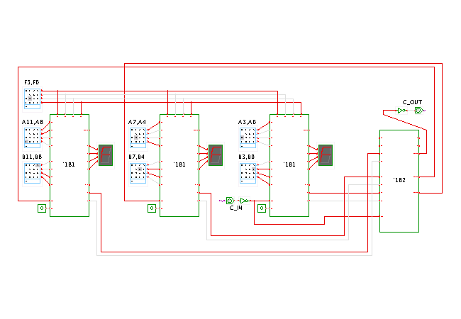
 DescriptionThis applet demonstrates a
fast 12-bit ALU
built from three 4-bit 74181 ALU chips and one 74182 carry-lookahead
generator chip.
The internal structure of the 74182 chips is shown in the next applet.
Click the input switches, or type the following bindkeys:
'f' to select the ALU function,
'c' for carry-in,
and '1','2','3','4','5','6' to control the hex-switches.
The initial value of the function selection hex switch is F=9, which selects the A+B+C_in ALU operation. The data input switches are set to the values A=0xC98, B=0x368, and C_in=0, which results in the ALU output value of S=0x0FFF. You can now click the C_in input switch to add a 1, and the ALU output becomes S=0x1000 (note the C_out). Naturally, you should play with the input switches and select your own input values.
The idea here is to connect the (X,Y) carry-lookahead outputs of the 74181 ALUs to the corresponding (Xi,Yi) inputs of the 74182 carry-lookahead generator, while the output signals of the 74182 are connected to the corresponding carry inputs of the 74181 chips.
Note that one 74182 is sufficient to connect to four 74181 chips, allowing a full carry-lookahead implementation of a 16-bit adder. Also, multiple 74182 chips can be cascaded in order to provide a carry-lookahead scheme for larger bit widths; for example, five 74182 (organized as a tree of four chips in the first level and one chip for the second level) can connect to sixteen 74181 chips for a 64-bit ALU. In bipolar TTL technology, the resulting 64-bit adder has a typical delay of just 60 ns, while a single 4-bit addition already takes 24 ns and the 12-bit single-level CLA addition shown in this applet requires 36 ns (data from the Texas Instruments TTL databook). Run the applet | Run the editor (via Webstart)