
 |  |
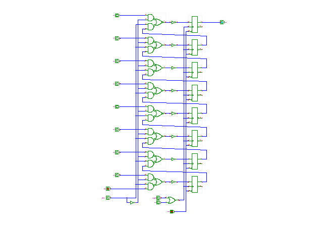
 DescriptionA demonstration of the TTL-series 74166
8-bit parallel-load serial-out shift-register.
The circuit consists of 8 edge-triggered D-type flipflops and a few gates connecting the flipflops. The /CLR input allows resetting the register. The CLK and CLK_INH inputs are connected via an OR-gate to the clock inputs of the flipflops. Therefore, either input can be used as the clock signal, and tying one of those inputs to high will disable the register.
When SH/nLD is high, the register contents is shifted on the rising clock edge, with the first flipflop loaded from the SER serial input. Only the output from the last flipflop is connected to the Q7 (QH) output pin.
When SH/nLD is low, the register contents is loaded from the eight data inputs D0 .. D7 (also called A..H) on the rising clock edge.
Run the applet | Run the editor (via Webstart)