
 |  |
 Description
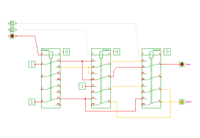
This circuit demonstrates a full-adder built with three relays.
Three identical relays with four changeover switches each are used,
to slightly improve the clarity of the schematics.
An actual implementation might avoid the unused switches.
Click the input switches or type the ('a','b','c') bindkeys to control the circuit and watch the behavior.
Each input of the full-adder (A, B, C=carry-in) is connected to the coil of one relay, with the other end of the coils connected to ground. The upper switches of the relays are used to calculate the SUM output,
SUM = A + B + C = A xor B xor C
As shown in the previous polarity change applet, two switches of the B-relay are used to realize the polarity changer required for the three-input XOR.
The lower switches are used to calculate the carry output signal, based on the following logical expression:
COUT = (A & (B | C)) | (B & C)
The third contacts of relays B and C are used for the (B & C) term, while the fourth contacts are used for the (B | C) term. Note that we cannot share the first contact of relay A (already used for the SUM output), because the resulting functions would be wrong due to feedback.
Obviously, larger adders can be built as a cascade of multiple one-bit adders, and subtraction is possible via two-complement's addition. Please see the arithmetic chapter of the applet collection for details and the different variants of adders.
Run the applet | Run the editor (via Webstart)