
 |  |
 Description
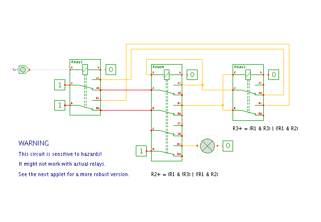
This applet demonstrates a toggle-flipflop built from three relays.
Due to the high cost of relays, a variety of flipflop circuits have been proposed over the years. Most of these employ additional components like capacitors and diodes and exploit "analog" tricks to reduce the number of relays. For example, see James Favell, a two-relay flip-flop, J Exp Anal Behav. 1969, Vol. 12, p.190, for a toggle-flipflop built with just two relays. The capacitor is essential for the operation of the flip-flop, and it must be dimensioned as a compromise between relay coil resistance and required switching time. You will need Spice or a similar analog simulator to study such circuits.
The circuit shown here uses three relays, but it is purely digital and requires no extra components. However, the circuit shown here is sensitive to hazards, and relays are especially prone to expose hazard conditions. First, the switch-on and switch-off times of a relay can differ by a wide margin. Second, the different contacts of a relay don't switch at exactly the same time. Third, there are significant variations between different relays, even of the same type. Be warned that the circuit shown here may not work with actual relays depending on their relative switching speeds. The next applet demonstrates a more robust circuit, which also uses three relays (but requires nine switches). Finally, we also have yet another flipflop, a symmetric structure built from four relays (and two diodes).
Click the input switch or type the 'c' bindkey to control the circuit and watch the resulting behavior.
The circuit shown here uses three relays. The flipflop state is maintained by relays R2 (middle) and R3 (right), where R2 changes state on the rising edge of the clock input signal, while R3 changes state on the falling edge. The first relay is directly driven by the clock input and provides two electrically isolated changeover switches. This relay could be replaced by a corresponding switch.
The toggle-flipflop itself is based on the following function table:
  R2  R3  CLK  |  R2+  R3+
 --------------+-----------
   0   0    0  |  0    0
   0   0    1  |  1    0
   0   1    0  |  0    0
   0   1    1  |  0    1
   1   0    0  |  1    1
   1   0    1  |  1    0
   1   1    0  |  1    1
   1   1    1  |  0    1
Standard minimization yields the logical functions to control the two relays:
  R2+ = (R1 & !R3) | (!R1 & R2)
  R3+ = (R1 &  R3) | (!R1 & R2)
Due to the use of the implicit wired-OR function (parallel connection of contacts), we cannot share the (!R1 & R2) term between both functions. Instead, two separate contact-pairs are required to generate the term twice, one for each relay.
While the R2+ and R3+ signals could be used as the flipflop output, it is more common in relay circuits to provide separate switches to drive the circuit load (here, a single lightbulb).
Please see the next applet for the modified more robust circuit, which should work with actual relays.
Run the applet | Run the editor (via Webstart)