

Gallery
Click on the links/thumbnails below to load some larger screenshots for each example.
|
|
|
|
Gallery
|
This page presents some examples for the HADES simulation
framework, from simple gate-level circuits with a handful
of simulation components to full system-level designs.
Click on the links/thumbnails below to load some larger screenshots for each example.
|
|
Simple examples
|
|
|
This example shows the HADES circuit for a simple D-type latch, built from for two-input NAND-gates. While running an interactive simulation, the user can click on the Ipin-components to switch the input values and watch the resulting output values on the Opin-components. Also, the simulation is running in 'glow mode', where the logical values on each signal are encoded by colors, which allows to watch the circuit behaviour 'at a glance'.
|
|
| This example shows some of the interactive I/O components, namely switches, pulse switches, HEX-switches, clock generator, power-on reset, LEDs (selectable colors), output-connectors with LED, and a seven-segment display. Note that the displays are still active, though glow-mode is off. | |
| A four-bit Hamming encoder and decoder, coupled by a transmission line with user-settable faults. Again, glow mode is used to visualize the operation of the circuit. Graphical objects like lines and labels a inserted into the design schematic to explain the circuit. Additionally, the screenshot shows the HADES 'tip of the day' window. | |
|
A Carry-Save-Multiplier circuit designed on RT level.
The example shows some of the HADES register-transfer level
components like registers and the main adders,
as well as custom components like the n-1-bit AND for the
multiplication and the three-input carry save adder.
All input values can be set by the user to study the behaviour
for different inputs.
Also, note the embedded state machine component in the lower left which controls the CSA with all its components. In interactive simulation, both the current machine state and the active transition are highlighted. |
|
| This example presents the flexible ALU from the RT library and its user interface, which allows to select the bit-width and the operation to perform for each of up to sixteen different ALU opcodes. As part of our 'Rechnerbaukasten' (German for 'computer construction kit'), this ALU and related simulation models enable users to easily model many existing computers, as well as their own designs. | |
|
System level and cosimulation
|
|
|
The main schematic for a radio controlled clock,
which decodes the time information broadcast by the
German DCF77 sender near Frankfurt.
With its separate blocks for decoder state machine, decoder
shift registers, and the 'standard' clock circuitry,
this design consists of about 1000 components in
three levels of design hierarchy.
Also, note the behavioral model for the DCF77 sender in the lower left. Not shown in the screenshot is the user interface of the DCF77 component, which allows to specify the date and time to transmit. |
|
|
A MIDI controller design that demonstrates
system simulation and HW/SW-cosimulation
with the PIC16C84 microcontroller.
Besides the Hades design, the screenshot also includes the
user interface of the processor core with disassembled program memory
and waveforms showing the last MIDI transmission.
The microcontroller is connected to a multiplexed seven-segment display with three digits, a multiplexed keyboard with twelve switches, and a midi-compatible open-drain driver. The software running on the microcontroller scans the keyboard (polling) and generates MIDI program change messages corresponding to the user-selected program number. Note that the controller has to drive the segment lines to display the program number, and to release them during reading of the keypad status. Simulation is only possible due to the usage of the IEEE stdlogic1164 logic model, together with the pullup components on the segment lines. |
|
|
RT-level model of PRIMA, the primitive machine - a minimal
von-Neumann machine used for teaching in our digital-systems
lecture.
The datapath with memory, ALU, and accumulator is shown on the
right. The control logic with program counter (PC), instruction
register (BR, Befehlsregister), and address register (AR)
is on the left. The block on the lower left contains the
sequencer logic.
The image shows the complete processor logic including all control wires. For visualization of data-transfers, it is probably better to hide all the control-lines and to show the register and memory locations affected. This is easily done via a small JPython script. Note the visualization of the buses, with different colors corresponding to the current data values on the buses. Also shown are the property editor for one of the registers and our memory editor, which highlights the last read (green) and write accesses (magenta). |
|
|
An ultrasonic range detector built with the PIC16C84 microcontroller,
transmitter/receivers, and alphanumeric LC-display.
The analog components of the complete design are modelled by a
digital adjustable delay line (top right).
Idea and software for this design were published by
EPE online magazine.
The controller creates 40 KHz pulse signals to drive an ultrasonic transmitter. The reflected ultrasonic signals are received by a corresponding sensor, amplified, and fed back to the interrupt logic of the processor. The processor calculates a distance value based on the arrival time of the reflected signal and current temperature, which is displayed on the LCD. |
|
|
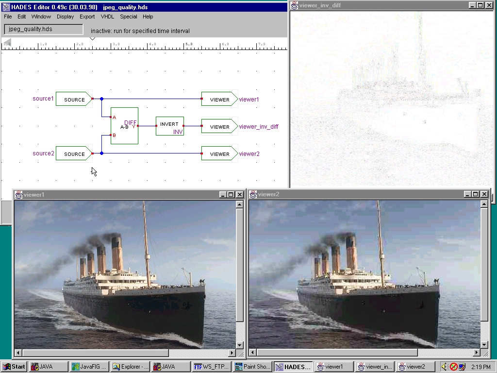
A simple image processing setup.
Two image sources are connected to image viewers each
and to a filter cascade consisting of a difference filter,
an inverting filter, and an image viewer.
When fed with two JPEG images of the same subject but of different quality, the resulting difference image illustrates the behaviour of the JPEG compression algorithm. (You should view this image on a high-color or true-color display, otherwise the details will be lost due to dithering by the WWW-browser.) |
|
|
HADES tools
|
|
| This screenshot demonstrates the HADES waveform viewer, codenamed Styx. Shown are example waveforms for the MIDI controller design above, at a moment where a MIDI program change message is transmitted (starting near t=8.45 milliseconds). The MIDI output signal is on top, with the PIC microcontroller I/O signals below, and the clock input at bottom. | |
| An example screenshot from our design and library browser, while exploring the standard basic gates library. Not shown are the search and WWW capabilites of the browser. | |
| A screenshot of our state machine editor, called JavaFSM. It supports Mealy and Moore automata with unlimited number of states. All standard logical operations are allowed to define transitions. The example shows a traffic-sign for a simple two street crossing. For another example of a state machine component inside a HADES design, see the CSA multiplier. | |
|
07.08.2000
Impressum
|
http://tech-www.informatik.uni-hamburg.de/applets/hades/html/gallery.html |